Power Averaging to Save Weight, Cost, and Space
In most applications, the power supply is sized as if the load is on continuously. But there are many applications where a load will draw power from its source in short bursts. The load is on for a short duration then turns off and then this cycle repeats. If the load is 3Kw and is on for 1ms and off for 5ms, the supply is configured for 3Kw even though the average power in this case is only 500 watts.
In applications where size and weight are critical and the load is only on for a short duration and is repetitive, the power system can be sized for the average power delivery by using a current limiting converter and a capacitor to supply peak power needs. When configuring such a power system, the designer must take into account the current limit, power limit, and stability of the power supply as well as sizing the capacitor properly to keep the voltage drop at the load within its tolerances. Applications such as pulsed amplifiers, flashing LED lights, and reclosures can take advantage of power averaging to reduce cost, space, and weight within the system.
But as system power levels increase, many designers are finding it difficult to stay within space and weight constraints for the power supply in these types of systems. When designing the power supply for continuous operation at peak power even though the average power is much less, support circuitry such as bypass caps, heat sinks, and system fans would need to be considered. This support circuitry takes up more system real estate and makes it even more difficult to stay within space and weight constraints. Designing the power system for the average power can be a better alternative.
Many dc power systems that are configured with dc-dc converters are designed to regulate voltage up to a maximum power level and have a maximum current and power rating. If the load tries to draw more than the rated current out of the supply, the supply will typically go into a current limiting mode that will either fold back the output voltage of the supply or the supply will shut down and restart. The current limit is typically set just above the maximum rated current so at the voltage set point of the converter, full power delivery can be achieved. A converter rated for 500 watts at 48 VDC will have a maximum continuous current rating of 500 watts/48VDC or 10.4A. The current limiting feature may start at 13A. The current limiting feature is typically designed for load faults only where the converter will see current limit only a few times in its life. If the converter isn’t designed to go into current limit as a normal mode of operation, you can stress components within the converter and shorten the life of the power system.
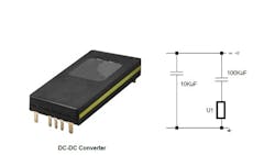
If the load draws more than the maximum current but below the current limit at the voltage set point, then you can overpower the supply and cause eventual power system failure. So a 500 watt converter at 48 VDC with a current limit set at 13A will be overpowered at up to 624 watts before current limiting starts. The typical configuration for a power averaging supply is shown in Fig. 1. The dc-dc converter is sized for the average power and the capacitor is sized to deliver the peak power while keeping the POL converters or load voltage within its specifications. U1 can be a simple circuit that switches in bulk capacitance during converter start up.
The large bulk capacitance can cause many complications for the dc power system. At turn-on the larger capacitor, which in many cases can be in the thousands of microfarads, can draw the dc supply into current limit. Many power systems can be configured with an external current limiting circuit if the supply isn’t designed to go into current limit as a normal mode of operation. The external current limiting circuit will keep the supply within its maximum current and maximum power ratings. These circuits are typically powered from the output voltage of the dc converter. At startup the output voltage powering the circuit will be zero and the circuit will be inactive and over current events can take place. The designer can pre-charge the capacitor or add series resistance that limits the current at startup. The series resistance can be shorted out once the external current limiting circuit is active. Pre-charging and current limiting circuits can be complex and they take up valuable board real estate. The external current limiting circuits must also be fast enough to catch an over-current event. This can be challenging because even a few switching cycles can cause an over-current event.
When the dc supply successfully powers up by safely charging the capacitor the power system must be stable. With some dc-dc converters, the large capacitor can destabilize the voltage control loop, which can cause supply or system failure. The power designer can overcome this potential stability issue if he has access to the control loop of the power system. Some dc power systems give the user access to the control loop so they can design the power system to work with a large capacitor. If the control loop is modified, the design must take into account the startup conditions as well as stability during operation.
The circuitry around the module can become very complex if the power converter isn’t designed to handle a large capacitor at its output. There are dc converter modules (DCMs) that are designed to handle large amounts of capacitance at their outputs. DCMs are inherently designed to operate within their maximum current rating and power rating even when driving capacitance values as large as 10KuF and more if the additional capacitance is switched in during start up. The DCM has a safe current limiting feature that can be used at the rated voltage of the supply. The current limiting feature can safely operate at the voltage set point of the module because it can deliver more that its rated power for short durations.
At startup the DCM will drive the capacitor up to voltage while staying within its safe operating area. Once the capacitor is charged, the control loop of the converter is design to be stable during normal operation. If the application is designed for power averaging, the initial power burst into the downstream POLs will be greater than the converter’s capability. The POL input current will be delivered from the voltage source that has the largest potential. Due to the ESR of the capacitor the converter’s output can have the larger potential and will deliver the initial surge of current until its output drops because of current limit. DCMs are designed to handle a surge current until its internal current limit takes over. Once the DCMs voltage drops, the current demand will then be satisfied by the capacitor. The capacitor can be sized to deliver much more current than the dc converter module. Once the POL or load current demand is over, the dc converter has to recharge the capacitor to its initial voltage so it can be ready for the next current demand.
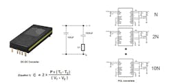
Power averaging configurations are very effective when the POL converter or load can tolerate a wide input voltage range. This is typically the case where the load is another regulating device or several regulating devices. The capacitance needed for the application can be represented by Equation 1 in Fig. 1.
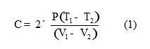
Where:
C = Capacitor value in Farads
P = Power delivered by the capacitor in watts
T1 - T2 = Load demand duration in seconds
V1 - V2 = Voltage drop across the capacitor during power delivery
When the POL or load demands power, the capacitor will deliver a greater portion of the load current because the dc converter will go into current limit feeding the capacitor and the load. As the capacitor delivers the POL or load current, its voltage will begin to fall. The capacitor must be sized so that the voltage across the capacitor stays within the input voltage range of the POL converter.
To minimize the capacitance needed the designer can charge the capacitor to the POL’s maximum input voltage and allow the power draw over the power duration to operate the capacitor down to the POL’s minimum input voltage.
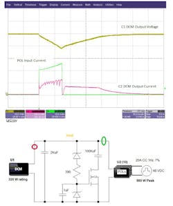
Figure 2 shows a scope plot and block diagram of a power system designed for power averaging. In this example, the dc converter module has its output set to 50 VDC and the converter module is rated for 320 watts of continuous power. The downstream POL converters are supplying a total 20A at 48 VDC or 960 watts of load power. The load frequency is 1Hz and the duty cycle is 7% so the load is on for 70ms. When the POLs begin to deliver power to the load, they draw energy from the 100KuF capacitor and the DCM. The DCM will go into protective current limit and the capacitor will supply the bulk of the power with the DCM in current limit. After the load demand is complete, the DCM will recharge the capacitor to its initial voltage.
Supplies configured for power averaging are very effective for reducing the size, weight, and cost of power systems where the load is on for a short periodic duration. The support circuitry can be minimized if the dc converter module is designed to operate safely within its current limit and power limit maximums. Sizing the power system for the average power also helps eliminate the support circuitry and hardware needed for power systems sized for continuous peak power delivery. This saves also helps the designer stay within the system space and weight constraints.
About the Author
Comment About the Article
To join the conversation, and become an exclusive member of Electronic Design, create an account today!

Leaders relevant to this article: