Low-pin-count test helps manage test cost
The ability to control test cost while design sizes have grown exponentially is a success story that relies on the invention and continuous improvement of embedded test compression. One way test compression controls test costs is to allow the application of more test data over fewer test pins. Using fewer test pins is important because while design sizes grow exponentially the number of pins grows linearly (Figure 1). The result is less available bandwidth for test pattern application. So, to control the increase in test cost, it helps to compress the test patterns and apply them in fewer cycles with fewer test pins.

But what happens when a chip doesn’t have enough pins even to apply compressed patterns while meeting test time and cost goals? In the case of these extremely pin-limited devices, there is the option of using special low-pin-count test (LPCT) controllers in conjunction with test compression. LPCT controllers further reduce the number of pins needed for test while maintaining test quality.
What drives the increase in manufacturing test cost?
IC test costs are directly proportional to the test times. On the design side, the test time depends on two major factors:
- the amount of testing that needs to be done, which corresponds to test data volume, and
- the bandwidth available for test patterns application, which corresponds to the number of test pins.
The amount of testing that needs to be done increases with the number of fault sites to test, which depends on the number of transistors and the use of advanced fault models required to meet test quality standards, such as those defined by ISO 26262. The bandwidth for applying test is a factor of how many pins are available. Because pin count increases linearly as transistor count increases exponentially, there are relatively fewer pins that can be dedicated to test on larger designs.
Aside from the design factors that affect test cost, the cost of the automatic test equipment (ATE) is a significant line item in test cost. The cost of an ATE is nonlinearly proportional to the number of pins it can support, operating frequency, pin electronics, and memory per pin. The costs involved in replacing or enhancing a tester’s capability to support more pins or data memory directly affect the profit of a product. Test compression is a great solution to controlling test costs because compressed patterns can be applied in fewer test cycles with fewer test pins while still achieving high test quality.

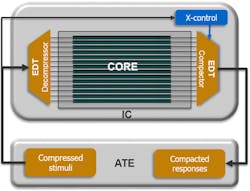
However, ICs are increasingly being restricted to very few test pins at the chip level by design. For many of these designs, test compression alone may still meet low pin count requirements. Figure 2 illustrates embedded test compression. Some scan-compression tools can apply high-quality deterministic test patterns with as few as one scan channel. This can greatly simplify top-level routing for cores and reduce the tester interface for chip-level, wafer, and package tests. Aggressive compression using only one or two channels can be achieved with dramatic results.
Another option for low pin count test is to use modified boundary-scan cells called RPCT (reduced pin count test) cells to access the design’s primary I/O pins. This eliminates the need for the tester to connect to the primary input and output pins directly.
For designs that need more than compression or RPCT, there are LPCT controllers. One of the three types of LPCT controllers described below will enable designers to reduce the number of pins needed for high-quality manufacturing test. All types of LPCT controllers can share their pins with existing functional pins.
Type 1 LPCT controller

The basic type of LPCT controller provides higher scan-data compression with high-quality testing and lower pin count. This controller is useful for cases in which the design has enough top-level pins for the test logic but the test engineer wants to maximize scan compression by allocating as many pins as possible for scan data. Rather than using top-level test pins to drive the edt_clock and edt_update signals, the controller generates these signals internally, effectively providing more pins for applying test data which reduces test data volume and test costs. The controller adds about 14 logic gates. A high- level architectural view is shown in Figure 3.
Type 2 LPCT controller

The type 2 controller generates the two control signals just like the Type 1 controller, and also uses a four- or five-pin TAP interface to control all scan hardware. The ability to test the design deterministically using only the TAP ports makes it possible to test the design using a debug board in-system as well as on the ATE. The test patterns normally applied to the primary I/O of the device can now be compressed as part of the scan patterns stored on the tester. Figure 4 shows a high-level view of how a single ATPG scan channel and a boundary scan register are controlled through the TAP ports.
Using this technique on sub-block and/or core applications, large amounts of test data can be delivered to the core in a small amount of time and with few connections to chip-level pins. The area of this type of test controller is about 20 gates.
Type 3 LPCT controller
A three-pin LPCT controller is useful for low-power and extremely test-pin-limited applications such as image-sensing ICs.

The requirements for using only three digital pins (scan in, scan out, clock) with test compression are to maintain high compression, provide an X-tolerant solution, maintain the same high stuck-at and transition fault coverage, and maintain diagnosis capability of compressed patterns. All of these requirements can be met using the type 3 LPCT controller that generates all necessary signals internally. A high-level architectural view of this test controller hardware is shown in Figure 5.
This LPCT controller has demonstrated high data and test time compression ratios of 65X with no impact to test coverage or test quality. The area of this type of test controller is about 1,400 gates.
More reasons to use LPCT
There are other good reasons to reduce the number of test pins:
- Reduction of top-level routing congestion. Today’s modular design practices require a reduction in the number of connections between cores and top-level pins. Applying test patterns to each block using one or two channels significantly reduces routing congestion.
- Managing pin limitations. Many applications require fewer pins even as gate counts increase, and the increase in analog pins limits the number of digital pins available for test. Similarly, mixed-signal designs with small digital content may have as few as three digital pins, greatly complicating scan test.
- Improving hierarchical ATPG. In hierarchical ATPG, patterns are generated individually at the core level and then remapped to the top level. These cores can be tested in parallel with patterns merged at the top level or sequentially depending on the number of top-level test pins. Since LPCT allows for reduced channel I/O at the core level, it enables patterns from more cores to be merged at the top level.
- Cutting ATE costs. ATE equipment is expensive so test managers are smart to extend the life of existing testers, which are limited in the number of pins they support, by using a smaller tester interface.
- Improving wafer test. One of the challenges of wafer test application is the number of contacts that the test head must make with each die on the wafer. Each additional contact point results in additional cost due to the required precision and accuracy and the risk of poor contact. By minimizing the test and functional interface requirements, LPCT addresses these concerns.
- Performing multi-site testing. A smaller test interface is required for effective application of the same test patterns to multiple devices in parallel. This technique, called multi-site testing, multiplies the value of scan compression by simultaneous test data application and observation. LPCT increases the number of devices that can be tested in parallel.
Summary
In combination with test compression, LPCT is an effective solution for managing test costs by reducing test-data volume, test time, and ATE costs while maintaining high-quality manufacturing test on pin-limited designs. The LPCT controllers have minimal impact on design and test overhead, and the controller logic generation and insertion is automated by ATPG compression tools.
About the Author
Rahul Singhal
Product Marketing Manager, Synopsys Inc.
Rahul Singhal is a Product Manager for TestMAX DFT at Synopsys. His focus is on the industry requirements in the area of test compression, ATPG, and DFT for AI architectures. He developed and presented a tutorial on DFT for AI chips and has co-authored multiple papers, posters on DFT, and test in leading IEEE conferences. Rahul received his MS in Electrical Engineering from Portland State University and a BS in Electrical Engineering from Purdue University.
Comment About the Article
To join the conversation, and become an exclusive member of Electronic Design, create an account today!

Leaders relevant to this article: