Understanding IF Bandwidth In RF Signal Analyzers
One extremely important yet not widely known characteristic of today’s high-performance RF signal analyzers is their use of a range of intermediate frequency (IF) filter bandwidth settings. IF bandwidth is a key factor in the selectivity of the instrument. Sometimes, it can have a significant impact on the measurement result. To understand the effect of IF bandwidth on measurement performance, it’s worthwhile to first review the architecture of the modern RF signal analyzer.
Related Articles
- Understanding Your Signal Analyzer's Dynamic Range
- Understanding Signal Analyzer Architectures
- What's Inside Your RF Signal Analyzer?
The modern “spectrum analyzer” is really just a vector signal analyzer (VSA) that uses up to three mixing stages to downconvert a signal from RF to baseband (Fig. 1). The signal analyzer executes the “spectrum” portion of the spectrum analyzer digitally simply by applying a complex fast Fourier transform (FFT) to the baseband waveform.
Instantaneous Bandwidth And The Spectrum Sweep
In most modern signal analyzers, a third IF filtering stage is often implemented with a bank of filters, each with different bandwidths and centered at the same center frequency. The variability of this IF filter stage gives engineers the tradeoff of wide instantaneous bandwidth versus better dynamic range.
In some applications, wide IF bandwidth is highly desirable. For example, modulation quality measurements such as error vector magnitude (EVM) require the signal analyzer to capture the entire modulation bandwidth to demodulate the signal.
This file type includes high resolution graphics and schematics when applicable.
In other applications, such as a fast spectrum sweep, the instantaneous bandwidth of the signal analyzer directly affects measurement speed. Suppose one configures the signal analyzer to perform a spectrum measurement with a span of 10 GHz. In this case, the instrument divides the 10 GHz span into smaller “chunks” based on its instantaneous bandwidth. If the signal analyzer’s instantaneous bandwidth is 50 MHz, the instrument will perform 10 GHz/50 MHz = 200 individual spectrum acquisitions. Finally, the signal analyzer “stitches” each acquisition together in the frequency domain to present the entire span.
The choice of the IF filter bandwidth has a significant effect on overall measurement speed. Wider IF bandwidths translate to fewer individual spectrum acquisitions and faster measurement speeds. By contrast, narrow IF bandwidth configurations require more spectrum acquisitions for a given span and lead to longer measurement times. Although the drawback of a narrow IF bandwidth is longer measurement times, using a narrow IF bandwidth can significantly improve the instrument’s performance in some applications, such as measuring the adjacent channel power (ACP) for a modulated signal.
ACPR Measurement Fundamentals
Many wireless standards use some form of an adjacent channel power ratio (ACPR) measurement to characterize the interference from one channel into the adjacent channel. Strictly defined, ACPR measures the ratio of the power in a main channel versus the power in the adjacent channel. Note that for some cellular standards such as UMTS and LTE, the “ACPR” metric is called the adjacent channel leakage ratio (ACLR).
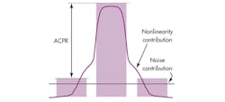
ACPR simply involves a measurement of the integrated power in the “main channel” in addition to a measurement of the integrated power in the “adjacent channel” (Fig. 2). Integrated power is equivalent to a “power-in-band” measurement, and the ratio of these two results is the ACPR.
One should also note that, in practical use, an RF signal analyzer’s ability to measure an “infinitely good” ACPR result is limited by both its inherent noise and nonlinearity. The signal analyzer’s inherent noise floor provides a noise contribution to both the main channel and the adjacent channel.
The noise contribution in the main channel is extremely small relative to the power of the channel and is therefore negligible. However, the noise contribution from the instrument’s inherent noise floor in the adjacent channel can significantly affect the measured adjacent channel power.
In most cases, the best-case ACPR result that a signal analyzer can achieve is often much better than the performance of the device under test (DUT). In some cases, though, the limitations of the instrument can affect the measurement result. For this reason, it’s worthwhile to understand how IF bandwidth can be adjusted to improve the signal analyzer’s capabilities.
Optimizing ACPR Performance
One can adjust simple VSA settings such as attenuation to trade off noise floor versus nonlinearity (see “Understanding Intermodulation Distortion Measurements”). One also can adjust the IF filter bandwidth to improve performance further, with the tradeoff of longer measurement times.
To understand this relationship, one must first consider that the analog-to-digital converter (ADC) of the signal analyzer has the potential to introduce a significant noise contribution to the measurement result. In fact, most signal analyzers use an amplifier in front of the ADC to maximize the ADC’s signal-to-noise ratio (SNR).
The signal analyzer’s ability to measure the low power levels in an adjacent channel often is affected by the ADC’s noise contribution. Since the ADC has a finite SNR, the signal analyzer typically will use a variable IF amplifier in front of the ADC to better utilize the ADC’s full dynamic range.
More IF gain essentially allows the ADC to “see” into lower ACP levels. However, too much IF gain produces ADC saturation, and the resulting clipping distorts the digitized signal. The trick, then, is to apply as much IF gain as possible without introducing distortion.
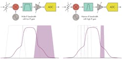
In modulated signals, the power of the signal is distributed over a specific bandwidth. A narrow IF filter bandwidth allows the signal analyzer to maximize IF gain by only allowing a portion of the RF signal to be present at the IF stage at any given time (Fig. 3). When the IF filter bandwidth is smaller than the bandwidth of the modulated signal, the bandpass filter effectively reduces the IF signal power by filtering out-of-band products.
As a result, narrrowband IF filters allow the signal analyzer to use higher IF gain without introducing the potential for clipping at the ADC. In addition to improving the SNR of the signal analyzer, narrow IF filters reduce the nonlinear distortion products introduced by the ADC. So when using a narrow IF filter, the signal analyzer is capable of better ACPR measurements with the tradeoff of longer measurement times.
Parting Thoughts
In many modern RF signal analyzers, IF filter bandwidth is simply an advanced setting that one can choose to adjust. Thus, although some might consider the processes of squeezing the last few dB out of an ACP measurement to be an art, it’s a fairly straightforward process. A basic understanding of the architecture of the modern RF signal analyzer empowers you to optimize its settings for a given measurement. For more detailed on measurement best practices using RF signal analyzers, visit www.ni.com/rf-academy/.
David A. Hall is a senior product marketing manager at National Instruments, where he is responsible for RF and wireless test hardware and software products. His job functions include educating customers on RF test techniques, product management, and developing product demos. His areas of expertise include instrumentation architecture, digital signal processing, and test techniques for cellular and wireless connectivity devices. He holds a bachelor’s degree with honors in computer engineering from Penn State University.
About the Author
David Hall
Head of Semiconductor Marketing
David A. Hall is the head of semiconductor marketing at NI and is responsible for developing and executing go-to-market plans for the semiconductor industry. His job functions include managing the semiconductor test business, identifying industry trends, and educating customers on best semiconductor test practices. Hall’s areas of expertise include ATE architectures, RF measurement techniques, digital signal processing, and best measurement practices for mobile and wireless connectivity devices.
With nearly 15 years of experience at NI, Hall has served in multiple roles throughout his career including applications engineering, product management, and product marketing for automated test and RF instruments. He has also held management positions in product marketing, which focused on employee development and meeting business results across products and application areas. Hall is a known expert on subjects such as 5G, the Internet of Things (IoT), autonomous vehicles, and software-defined instrumentation. He holds a Bachelor’s with honors in computer engineering from Penn State University.


