4½ Practical Uses for a Diode

The diode is a fundamental component you must understand if you want to grow your electronics prowess. So today, we’re going to take a quick look at what a diode is, then look at 4½ uses for a diode in your designs.
Author’s Note: To my knowledge there’s no use for just half a diode, so don’t get your hopes up.
Diode Refresher Course
If you’re reading this, you’re probably already familiar with diodes, so I’ll try to keep it interesting for you. The diode is generally the first nonlinear component one learns about. Resistors, capacitors, and inductors are all linear devices, meaning they can be characterized using a first order differential equation. As much as I want to geek out on the math right now, I’ll spare you; that’s what Wikipedia is for. So, what are diodes?
Diodes are nonlinear devices. They don’t follow Ohm’s law, and for circuit analysis you can’t replace them with a Thevenin equivalent.
Diodes are passive devices, which means they don’t need power to function.
Diodes are two-port devices. There’s just one input, the anode, and one output, the cathode (Fig. 1).
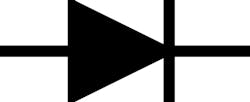
1. The circuit symbol for a diode, with the anode on the left and the cathode on the right.
Conceptually, diodes are quite simple. But, they’re extremely useful because of their V-I curve, shown in Figure 2. The X-axis is voltage, and the Y-axis tells us how much current can flow through the device when exposed to that corresponding level of voltage.
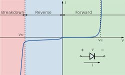
2. A diode’s IV curve.
Positively Biased Diodes
You should notice a few interesting things in Fig. 2. Let’s start on the right side of the Y-axis. At moderate positive voltages, a diode essentially acts as a short, but with a small voltage drop. This is usually called the “forward voltage drop,” but I’m sure its Mom has a cute nickname for it. Maybe “cut-in voltage” or simply “on voltage.”
You can see the forward voltage drop on the V-I curve in Fig. 2, around 0.6-0.7 V, where the current starts to ramp up. A 0.6/0.7-V drop is standard for silicon diodes, but for other types of diodes and materials, the forward voltage drop may vary.
You can measure this forward voltage for a specific diode using a multimeter with a diode testing capability. You can see that this diode has a forward voltage of roughly 0.62 V (Fig. 3).
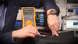
3. Measuring the forward voltage of a diode using a Keysight U1282A multimeter.
But what you need to remember is that when exposed to a moderate voltage—say 5 V—a diode will pass through 5 V minus the forward voltage. So, 4.3 V for a standard silicon diode. There are some methods for compensating for this drop, but that’s beyond the scope of this article.
Negatively Biased Diodes
Let’s now move to the left side of the Y-Axis in Fig. 2. When exposed to a negative voltage, there will be a nanoamp reverse current. You can generally approximate it as 0 A in most situations. That is, until you get to the other big swing on the VI curve, known as the breakdown voltage.
If your diode is exposed to a high level of reverse bias, you blew it. Often literally. Diodes essentially can’t hold up to that level of negative voltage and the device physically breaks down, allowing negative current flow.
Long story short, you can essentially think of a diode as a one-way conductor with a voltage drop. Enough preface, let’s look at a few different ways you can use diodes for your circuits.
Use #1: Rectifiers
Rectifiers have been covered ad nauseum by other sources, so I’ll be brief. The gist is that you can let through the positive voltages from an ac source while blocking or inverting the negative voltages.
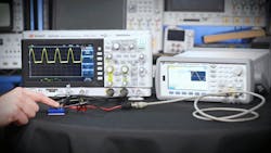
You can put together a halfwave rectifier with a single diode (Fig. 4).
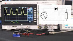
4. A half-wave rectifier circuit connected to an ac source. Notice the characteristic half-wave signal on the oscilloscope screen.
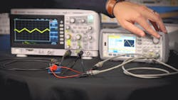
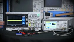
Or, you can create a full bridge rectifier with four diodes (Fig. 5). It’s worth noting you should use a differential probe when measuring a full bridge rectifier with an oscilloscope. Otherwise, you’ll ground half of your rectifier.
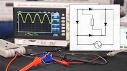
5. A full-bridge rectifier being probed with an oscilloscope and a differential probe.
Bring a capacitor into the mix, and you can do a couple things.
First, you can smooth out a rectifier (Fig. 6). However, it’s generally better to use an active voltage rectifier chip.
6. Here, a capacitor being switched in and out of a half-bridge rectifier circuit.
Second, you can build a voltage multiplier (Fig. 7). This is essentially a series of half-wave rectifiers. These are used for things that need high voltage but minimal current, like bug zappers and particle accelerators—or bug accelerators.
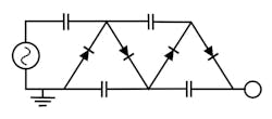
7. A crude voltage multiplier.
Use #2: Diode Logic Gates
You can build simple logic gates using diodes.
You can create an n-input OR gate or AND gate using 1 diode per input (Fig. 8).
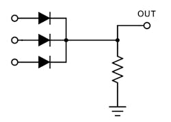
8. A three-input OR gate using diodes.
For more practical scenarios, you can do some less-standard “logic.” Take, for example, a battery backup system (Fig. 9). Using two diodes, you can pass either the intended voltage input (if present), or the battery source.
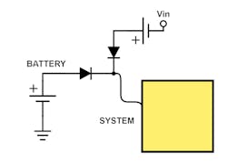
9. A crude battery backup system using two diodes.
In this situation, the diode is reverse-biased under normal conditions, so the battery stands dormant. When the source voltage is removed, the diode becomes forward-biased and provides power to the device.
Use #3: Diode Clamps
You can use diodes to limit the range of a signal. Essentially, you can pre-clip the signal by connecting a diode to a reference voltage or a voltage divider as shown in Figure 10.
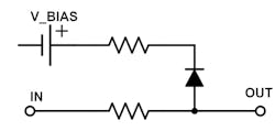
10. A simple voltage clamp. By adjusting the bias voltage, you can modify the clamping levels.
In Figure 11, we start with a standard triangle wave and the signal looks normal on the oscilloscope. But, when we ramp up the signal’s amplitude to a level above our threshold, the top of the signal starts to clamp. You can set the clamping threshold using the bias voltage, and adjust the strength of the clamp by varying the resistor value.
11. A clamped triangle wave shown on a DSOX1102G oscilloscope.
For better clamping, you can add a bypass capacitor. Or, you could turn to an active clamper circuit using an op amp or transistor circuit, but the simple diode provides an easy and cheap clamp. They are often used with sensitive inputs, like CMOS logic circuits, to prevent damage from static discharge.
Use #3.5: Diode Limiters
I’m only counting this as half of a use, because it technically falls under clamping. But, it’s different enough to warrant an extra 0.5.
Limiters, sometimes known as clippers, are a special type of clamp that limit the output to plus or minus the forward voltage with a setup like Figure 12. This can be used to help protect high-gain amplifiers or other sensitive circuitry from saturating.
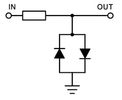
12. A diode limiter, also known as a diode clipper.
In Figure 13, a sinewave’s amplitude will be swept between 0 and 5 V.
13. An amplitude-swept sine wave fed through a diode limiter.
Use #4: Flyback Diodes
Flyback diodes are the pressure-release valves of the electronics world. Because inductors resist a change in current. you can’t just instantaneously turn them off—they’ll fight back against the control circuitry, which will damage it. This is known as “inductive kick.”
So, you can add a flyback diode in parallel with the inductor (Fig. 14). As I mentioned in a video about the time constant over on the Keysight Labs YouTube channel, this can cause a slower current decay than one might like. So, you could also use an RC snubber.
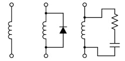
14. An inductor, an inductor with a flyback diode, and an inductor with an RC snubber.
It’s worth pointing out that this method won’t work if the inductor is driven by an ac source (like a transformer), because the diode will conduct on half-cycles. In that situation, you should use an RC snubber or something like a metal-oxide varistor.
Diodes Rock
This is just the tip of the iceberg when it comes to diodes. Are you using these or any other diode tricks in your designs? Let me know in the comments, on the Keysight Labs YouTube channel, or on Twitter!

About the Author

Daniel Bogdanoff
Oscilloscope Product Manager
Daniel Bogdanoff is the Product Manager for the InfiniiVision series of oscilloscopes at Keysight Technologies. He graduated from Texas A&M with a degree in electrical engineering. In his spare time, Daniel enjoys whitewater kayaking, mountain biking and playing various musical instruments.
Comment About the Article
To join the conversation, and become an exclusive member of Electronic Design, create an account today!

Leaders relevant to this article: