The Essentials of Logic Analyzers
Just as the oscilloscope is the instrument of choice for analog electronics, and the spectrum analyzer is preferred for RF measurement, the logic analyzer is the go-to instrument for digital system designers.
Equipped with multiple channels, the logic analyzer characterizes the data state and timing of a large number of digital signals. Typically, these digital measuring instruments offer 16, 32, 64, or a greater number of input channels that can be displayed in a variety of formats. Among these display formats are timing diagrams, state diagrams, protocol decodes, and assembly code.
Logic Analyzer Form Factors
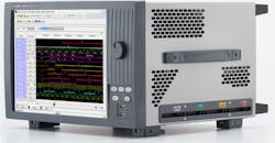
Logic analyzers come in a range of form factors, including instrument, modular, and computer-based packages. Instrument-format logic analyzers are housed in traditional, standalone cases just like an oscilloscope or spectrum analyzer (Fig. 1).
1. Keysight Technologies’ 16864A 136-channel portable logic analyzer comes in a standalone instrument chassis; others are available in modular or PC-based form factors. (Source: Keysight Technologies)
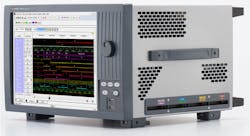
Modular logic analyzers are based on standardized modular PC cards intended to operate in a mainframe crate or chassis. They’re available with a fixed channel count per module; the maximum channel capacity is a function of the number of slots in the crate. Power and timing signals are shared between all of the modules in a crate (Fig. 2).
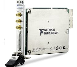
PC-based instruments are small modules connected to a PC using USB or Ethernet connections (Fig. 3). In recent years, logic-analysis capability has been incorporated into digital oscilloscopes, giving rise to “mixed-signal oscilloscopes” or MSOs. On top of that, instruments like the GoLogicXL-36 shown in Fig. 3 can be connected to an oscilloscope to add logic-analyzer trigging capabilities to the features of a scope.
Decoding the Logic Analyzer’s Display
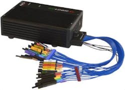
A logic-analyzer display consists of multiple channels of digital data plotted as digital state versus time (Fig. 4). This display from a 16-channel, PC-based logic analyzer shows a four-wire digital bus along with the three component signals of a SPI bus.
The digital bus has four component signals (D0-D3) combined with the bus state. The vertical scale is the logical state of each digital line, ‘0’ lower state or ‘1’ upper state. The state readout is the hex value of the parallel bus signals
The three SPI bus signals are the SPI data, clock, and chip select. The SPI bus readout shows the decoded value of the data contained in the serial SPI packet. The SPI packet is data that’s occurring during the eight-pulse clock burst while the chip-select line is in the low or ‘0’ state.
2. The 32-channel PXI-e 6545 from National Instruments is a good example of a modular logic analyzer. (Source: National Instruments)
Logic-Analyzer Operation
The logic analyzer, like the digital oscilloscope, is a digital instrument. It digitizes each input channel at a rate set by the analyzer’s clock rate. Unlike an oscilloscope, each channel of the digital conversion contains just a single bit. Is the signal above or below the user-set digital threshold? The resulting digitized data has a value of either 0 or 1. Standard threshold values for TTL, CMOS, or other user-set thresholds are between 0 and 7 V.
All digital channels are clocked simultaneously, and the parallel digital data is clocked into the acquisition memory. The acquisition memory has one row of memory for each digital input. The depth of the acquisition memory determines the duration of the measurement. Data is acquired continuously in the memory until the occurrence of a trigger event. At this time, the memory contents are displayed. If the logic analyzer is set in single trigger mode, the acquisition stops until it is re-armed. In normal trigger mode, the acquisition resumes, awaiting the next trigger event.
The user can set the trigger location so that it occurs in the center of the acquisition memory. By doing so, it’s possible to observe the data before and after the trigger. Therefore, if triggered by an anomalous event, the logic analyzer can show the conditions leading up to that event. Display zoom allows users to view selected sections of the memory contents.
Logic analyzers are triggered just like an oscilloscope. The trigger condition could be a simple edge transition of a single digital input or the presence of a preset logic state involving multiple digital lines. Common trigger events include specific data words, data words within specific ranges of values, after a preset number of events based on an event counter, or an external trigger signal. Conditional triggering, where a trigger event occurs only under a qualifying logic condition, takes place simultaneously. When the trigger event occurs, it locks the content of the acquisition memory, which is then displayed as explained previously.
Generally, two clocking modes are available in logic analyzers: asynchronous (timing) and synchronous (state) acquisition. Asynchronous clocking uses an internal clock of the logic analyzer that has a frequency several times greater than the device under test’s system clock. The measurement clock rate, which is asynchronous with the timing of the system under test, determines the time resolution of the timing measurement. It can determine the edges of the logic signals with a resolution equal to the period of the clock signal. It’s also able to detect glitches and other abnormal timing issues.
Synchronous clocking uses a clock source that’s synchronous with the device being tested. This mode captures the state of the digital signal only when its value is valid. It shows the progression of actual machine states in the system under test and ignores transitional conditions on the digital signal lines.
3. The PC-based GoLogicXL-36 logic analyzer can also be connected to an oscilloscope to complement its features. (Source: NCI)
Data Bus State and Serial Data Decode
As noted in Fig. 4, the acquired bus data can be viewed in a condensed form, where the data state of the parallel bus is displayed. The user usually has a choice of viewing the bus value in binary, decimal, hex, or ASCII format.
Serial data, such as the SPI bus in Fig. 4, can be decoded and read out in the same data formats for specific serial standards. The logic analyzer used in this example can decode SPI, I2C, or UART data packets. Higher-performance logic analyzers support many high-speed serial data standards, including PCI-Express, XAUI, Rapid IO, HDMI, and SATA, as well as many others.
Measurements
Logic analyzers offer a number of tools for making measurements on the acquired data. At a minimum, they offer cursors that can measure the time between events. More sophisticated logic analyzers provide measurement parameters such as frequency, period, pulse width, duty cycle, and edge count. Note that no amplitude-related measurements are made—that requires an oscilloscope. The parameters are fully automated and save a great deal of time over manual cursor placement.
Instrument Synchronization
Many logic analyzers can interface with a digital oscilloscope. When operated jointly, analog waveforms from the oscilloscope are synchronized with the digital data from the logic analyzer and displayed in common. Alternatively, MSOs now offer digital along with analog channels, and display both analog and digital signals on synchronized time axes.
Furthermore, software packages are available that integrate the logic-analyzer output with oscilloscopes and other instruments, enabling analysis of synchronized digital and analog data. Software options for some logic analyzers allow for processor emulation and code disassembly, permitting correlation of low-level hardware activity to source code.
Probes and Flying Lead Sets
Due to the logic analyzer’s large number of input channels, interconnection with the device under test is a major issue. Historically, logic analyzers have been equipped with “flying lead sets.” These ribbon-cable assemblies are terminated in individual wires. Often, micro-grabbers are mated with the individual leads as a means of connecting with circuit points. These lead sets work well for a moderate amount of channels, but become cumbersome for a large number of leads. Also, open wires and micro-grabbers add significant load capacitance and induction to the physical connection, which can distort high-speed signals.
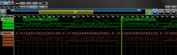
4. A typical logic-analyzer display shows a four-wire digital bus (D0-D3) and the three component signals of an SPI serial interface data (DATA), clock (CLK), and chip select (CS). The digital bus state (BUS1) is displayed along with the SPI bus decode (SPI Bus). (Source: ClariTek, using Teledyne LeCroy LogicStudio software operating in demo mode)
The trend in the industry is to use multi-channel probes that properly terminate the digital signals being measured. Such probes use multi-pin connectors, which requires that probe points be designed into the system being measured in order to bring the digital signal out to the mating connector.
Specifications
Logic analyzers come in a wide range of form factors, which determine the capabilities and cost of the instrument. All logic analyzers have a number of key specifications that determine the appropriateness of the units for the specific application. Key specifications include:
- Channel count: Specifies the number of digital signals that can be analyzed.
- Channel bandwidth: Determines the maximum speed of the logic families that can be measured.
- Threshold selections: Governs the compatibility with specific logic families.
- Maximum clock rate: Fixes the time resolution of the measurement.
- Acquisition record length: Controls the duration of the analysis.
- Trigger modes: Used to isolate the target digital events.
- Probe type: Determines the ease of connecting the logic analyzer and the integrity of the signal connections
- Measurement tools: Cursors and automated measurements help interpret acquired data.
Conclusion
The logic analyzer is an ideal instrument for debugging and verifying the operation of digital systems. It allows the simultaneous analysis of a large number of digital signals encountered in modern digital systems. Its timing-analysis capabilities are useful for investigating violations of system timing and finding transient events that lead to system failures. With appropriate options, it can help trace the execution of embedded software code.

About the Author
Patrick Mannion
Founder and Managing Director
Patrick Mannion is Founder and Managing Director of ClariTek, LLC, a high-tech editorial services company. After graduating with a National Diploma in Electronic Engineering from the Dundalk Institute of Technology, he worked for three years in the industry before starting a career in b2b media and events. He has been covering the engineering, technology, design, and the electronics industry for 25 years. His various roles included Components and Communications Editor at Electronic Design and more recently Brand Director for UBM's Electronics media, including EDN, EETimes, Embedded.com, and TechOnline.
Comment About the Article
To join the conversation, and become an exclusive member of Electronic Design, create an account today!

Leaders relevant to this article: