Make Great Oscilloscope Measurements
This file type includes high-resolution graphics and schematics when applicable.
Daniel Bogdanoff, Oscilloscope Product Manager, Keysight TechnologiesElectronic Design welcomes Daniel Bogdanoff, Oscilloscope Product Manager, Keysight Technologies, to the roster of Contributing Technical Experts. He will be giving his insights on oscilloscope fundamentals and trends, and the test-and-measurement field in general.
In oscilloscopes today, making a good signal measurement is easy. However, making a great measurement takes some expertise. As edge speeds increase and voltages decrease, your signal’s margin of error becomes smaller and smaller. So, making a great oscilloscope measurement could mean the difference between meeting and not meeting your design parameters.
Digital oscilloscopes have turned manual measurements into an automated process, allowing you to make adequate measurements quickly and easily. However, turning that good measurement into a great measurement requires a little extra knowledge and effort. Following some key best practices will give you much higher accuracy and confidence in your measurements. Signal scaling and bits of resolution will impact the quality of your measurement, so it’s crucial to understand how to get the most out of your oscilloscope.
Start by Making a Good Measurement
First, set up your scope to make a measurement. Simply press the “Measure” button on the front of your oscilloscope. The scope will then automatically display the requested measurement on the screen. You can configure the scope to modify the measurement parameters, track the measurement with cursors, and even display measurement statistics. To improve the quality of this measurement, consider the following best practices.
Signal Scaling
Proper signal scaling is crucial for optimizing measurements. The signal’s scaling on screen affects sample rate and bits of resolution, which in turn affects your measurement’s accuracy. Both horizontal scaling and vertical scaling influence your measurement in different ways.
Horizontal scaling
Horizontal scaling is important to consider when making time-dependent measurements. When you change the horizontal scaling (time-per-division) of your signal, you’re also changing the total signal-acquisition time. Signal-acquisition time in turn affects the sample rate of the scope. This relationship is described by the equation:
Sample Rate = Memory Depth/Acquisition Time
Memory depth is a fixed value, and the acquisition time is fixed by adjusting the time-per-division setting on your oscilloscope. As the acquisition time increases, the sample rate will have to decrease in order to fit the entire acquisition into the scope’s memory. Having an appropriate sample rate for time-dependent measurements (frequency, pulse width, rise time, etc.) is important.
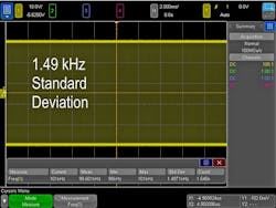
For example, take a frequency measurement of a known 100-kHz clock signal (Fig. 1). At 2 ms/division, we can see that the frequency measurement has an average of 99.6 kHz with a standard deviation of 1.48 kHz. Based on the standard deviation value, this gives us a measurement accuracy of about 1.5%. Notice that the sample rate is 100 Msamples/s due to the larger time-per-division setting of the scope.
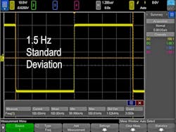
Looking at the exact same 100-kHz clock signal at 1.2 µs/division instead of 2 ms/division (Fig. 2), we see that the average measured frequency is 100.00 kHz and the standard deviation is 1.53 Hz. This gives us measurement accuracy of around 0.001%. Also note that the sample rate is 5 Gsamples/s, which is the maximum sample rate for the Keysight InfiniiVision 4000 X-Series oscilloscope being used.
By horizontally scaling the signal to only show about one period, we were able to maximize the sample rate and improve the standard deviation of our frequency measurement by a factor of 1000. While 99.6 kHz was a good measurement, our knowledge of horizontal-scaling techniques enabled us to make a measurement three orders of magnitude more accurate.
Vertical Scaling
Just as horizontal scaling is important for time-specific measurements, vertical scaling is important for vertically dependent measurements (peak-to-peak, RMS, max, min, etc.).
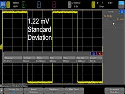
Take, for example, the same 100-kHz clock signal we discussed for horizontal scaling. This time we will look at a peak-to-peak voltage measurement (Fig. 3). At 770 mV/division, we see that the average VP-P value is 681 mV and the standard deviation is 18.1 mV.
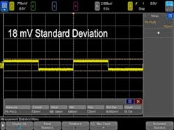
By simply increasing the voltage-per-division scaling (Fig. 4), the average value becomes 512.5 mV and the standard deviation becomes 1.2 mV.
Increasing the vertical scaling of the signal enabled a much more accurate VPP measurement with a standard deviation that’s 15 times smaller. Why does the vertical scaling have an effect on the measurements? Just as horizontal (time-dependent) measurements are affected by sample rate, vertical (amplitude-dependent) measurements are affected by bits of resolution.
Bits of Resolution
Bits of resolution describes the precision of an analog-to-digital converter (ADC). The higher the bits of resolution, the more vertical quantization levels an ADC can identify when sampling an analog signal.
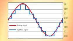
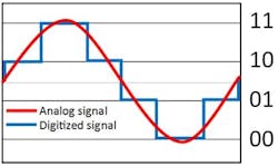
For example, Figure 5 shows a two-bit ADC. The analog-signal input is in red, and the quantized digital-signal output from the ADC is in blue. A two-bit ADC has four vertical quantization levels and doesn’t have the ability to be any more precise. So, the analog signal will be quantized down to one of four values.
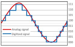
In a three-bit ADC (Fig. 6), we see that there are eight possible levels for the digital signal. This significantly increases the precision of the ADC, and the analog signal will be more accurately represented.
Most oscilloscopes have eight bits of resolution; the signal viewing area of the oscilloscope’s screen represents eight bits. A digital oscilloscope uses the quantized waveform to make measurements. So, the more accurately the ADC portrays the analog signal, the more accurate the measurements. Looking back at Figure 3, we see that by not scaling the signal to the full vertical height of the screen, we aren’t taking advantage of all of the oscilloscope’s bits of resolution. When we scaled the signal to maximize use of the oscilloscope’s resolution (Fig. 4, again), we were able to make a better VP-P measurement.
This has important ramifications, especially if you’re using more than one channel at a time. For example, it’s common to make power measurements using two channels (current and voltage). To make a great power measurement, you must scale both signals to the full height of the oscilloscope’s screen instead of stacking them above each other on the screen. If you only use half of the screen for voltage and the other half for current, the oscilloscope can’t use all bits of resolution on each waveform.
It is important to note, however, that the oscilloscope’s bits of resolution are just one part of the system, and the entire signal path must be observed to consider the total effective number of bits. This includes external factors such as probing and system noise, as well as internal factors such as your oscilloscope’s noise floor. If the system’s noise is high enough, an increased number of bits of resolution will only show noise.
Knowing how to best use your oscilloscope is crucial if you want to move from making good measurements to making great measurements. More accurate measurements further boost confidence in verifying and debugging designs. Understanding how to scale your signals properly to take full advantage of sample rate and bits of resolution is a crucial skill for success while testing and debugging.
About the Author

Daniel Bogdanoff
Oscilloscope Product Manager
Daniel Bogdanoff is the Product Manager for the InfiniiVision series of oscilloscopes at Keysight Technologies. He graduated from Texas A&M with a degree in electrical engineering. In his spare time, Daniel enjoys whitewater kayaking, mountain biking and playing various musical instruments.
Comment About the Article
To join the conversation, and become an exclusive member of Electronic Design, create an account today!

Leaders relevant to this article: