Make the Move from Module-Based Mixed-Signal Verification to UVM
Migrating from a module-based mixed-signal verification environment to the Universal Verification Methodology (UVM)—the industry standard for metric-driven, constrained-random verification—gives designers a mixed-signal verification framework that supports constrained-random verification. As a result, they’re better positioned to meet coverage goals and find corner-case problems.
This file type includes high resolution graphics and schematics when applicable.
This article discusses techniques used to achieve this transition, including proxy SystemVerilog interface task calls that outsource bus driving to existing module-based drivers, and Verilog configurations that can elect the desired abstraction level of the design under test (DUT). It also looks at a traditional directed test-based verification environment, pre-UVM. Then it examines how to augment the directed testing methodology with UVM, while maintaining backwards compatibility to the original approach.
A Pre-UVM Verification Methodology
Analog remains a significant force in many design environments. Typically, analog engineers are accustomed to analog-centric simulation environments. Designers generally create testbenches using schematic entry and multiple configuration views.
Waveform inspection has traditionally been a primary means of analog verification. In comparison, the advanced verification methodologies employed by verification engineers are heavy on the digital side. They are generally command-line driven and use object-oriented languages like SystemVerilog (Fig 1).
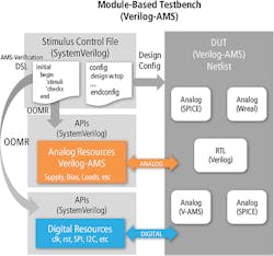
Since it’s impractical to maintain two top-level verification environments, one solution is to apply a digital-centric verification environment in which analog engineers can perform self-checking, top-level simulations. Such an environment can be created using a domain-specific language based on pre-processor macros and SystemVerilog APIs. An out-of-module reference from a test-case file is able to control digital and analog resources. Through Verilog configurations, users can select the DUT abstraction needed for each test case.
Because all of this information is centralized in a single file, each test case essentially becomes a SystemVerilog file passed as a parameter to a simulation launching script. In contrast, traditional flows usually require up to four views to describe the stimulus, design configuration, and simulation options.
In this environment, a hierarchical, single full-transistor netlist can be used for all simulations. After creating the netlist, all other simulation-related tasks can be performed outside the analog development environment using text-based files. All test cases can share the same pre-compiled netlist.
Add UVM to the Verification Environment
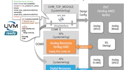
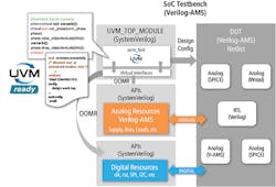
To bring UVM into the fold, it’s important that the UVM drivers use the same SystemVerilog APIs as the existing mixed-signal verification environment. To make this possible, the virtual interfaces referenced in the UVM drivers must command existing module-based APIs. Then, the UVM drivers can forward the transactions to the virtual interface. Legacy module-based drivers can take care of the actual signal wiggling (Fig 2).
The UVM top module consistently runs the same UVM_test to call an external virtual task. As the actual test scenario, this external virtual task is implemented in a separate file. The user can now take advantage of UVM while utilizing the same pre-processor APIs to generate directed tests. In other words, the user can execute existing legacy tests and create new directed tests with the traditional methodology. The only thing that needs to be done is to constrain the UVM transactions generated with a generic sequence and map them to the legacy API macros.
This new approach works with simple, as well as complex, UVM transactions. One example would be an SoC IC with a serial peripheral interface (SPI) that writes registers and a UVM driver that doesn’t handle SPI pins, only high-level transactions such as address, data, and read/write. In this case, the UVM transactions can be forwarded to the legacy module-based drivers to toggle sclk, cs, and mosi.
Benefits of UVM for Mixed-Signal Verification
Freescale integrated UVM in the design verification of a next-generation battery-monitoring IC. UVM offers better coverage and better detection of hard-to-find bugs in a mixed-signal SoC. The methodology is backwards-compatible with the traditional module-based framework.
With UVM, users can produce a substantial amount of test vectors with little effort. Digital designers are able to easily port block-level tests developed in UVM to the top level—a previously unachievable task. In addition, the UVM register layer can be integrated at the IC top-level environment, thus saving substantial development time in verifying register sequences.
Freescale uses UVM/mixed-signal building libraries of reusable verification components (UVCs), which consist of monitors and drivers as a foundation. The library is extended by creating custom models; for example, unified tests for analog that match with the company’s SoC IC blocks’ specifications.
When using a coverage or metric-driven approach, simulation throughput is crucial. To collect enough metrics, computer farms execute large numbers of parallel simulations. Modeling with real number models (RNMs), Verilog-AMS Wreal, or in SystemVerilog IEEE 1800-2012 is an effective way to increase the speed and effectiveness of simulations.
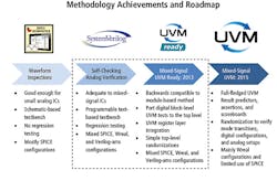
Analog designers at Freescale have adopted this new methodology (Fig. 3). The company's current “UVM-ready” method provides a gradual transition to the new verification paradigm. Designers familiar with the traditional verification environment can continue to develop directed tests using mixed-signal configurations in SPICE/behavior Verilog-AMS abstraction. Design-verification engineers could complement top-level verification with UVM-powered, constrained random stimulus using RNM configurations. Note that in principle, UVM can be used to verify the design in Spice abstraction; however, runtimes become uninviting.
Integrating UVM into a traditional directed-testing verification methodology brings the benefits of better coverage and better detection of hard-to-find bugs. As a result, both analog-centric and digital-centric verification engineers can be productive at the critical top-level verification phase. The UVM/mixed-signal methodology reduces the coding effort in the long run by introducing reusable stimulus, coverage, and checks in a standard methodology.
This file type includes high resolution graphics and schematics when applicable.
Cadence provides all of the mandatory components to apply the UVM/mixed-signal methodology, via its Virtuoso Analog Design Environment. The Virtuoso environment has all of the functions needed to explore, analyze, design, and verify analog and mixed-signal SoCs. In addition, it offers a new unified netlister technology that speeds up the process of netlisting and elaborating a simulator snapshot with Cadence Virtuoso AMS Designer Simulator. The resulting flow supports SystemVerilog, SystemVerilog-DC, SystemVerilog assertions, Verilog-AMS, VerilogHDL, and UVM. Also, because the flow is open, mandatory customizations are possible for any application.
Arthur Freitas leads the definition and implementation of analog/mixed-signal verification methodology at Freescale’s analog product division. He holds an MSc in microsystems engineering from the Furtwangen University of Applied Sciences.
André Baguenier Desormeaux is a Senior Staff Product Engineer for analog and mixed-signal circuit simulation at Cadence Design Systems, where he helps designers find success with their analog/mixed-signal SoC verifications.


