Mitigate Error Sources to Maximize Current-Measurement Accuracy
This file type includes high resolution graphics and schematics when applicable.
Monitoring the current consumed in electronic systems has become critical as more functionality packs into tighter areas. Current-sense amplifiers (also called current-shunt monitors) are ideal for monitoring current consumption to maximize measurement accuracy. Achieving the highest possible accuracy requires making some key decisions with respect to device selection and system implementation. In this article, I’ll look at some of the key factors affecting current-measurement accuracy and how system requirements affect device selection.
First, you should understand the sources of potential errors. Though not comprehensive, the list below highlights some of the key contributing factors:
Amplifier-related error sources:
• Input offset voltage (VOS) and VOS drift
• Common-mode rejection ratio (CMRR)
• Power-supply rejection ratio (PSRR)
• Gain error and gain drift
System error sources:
• Gain setting passives tolerance, matching and drift
• Printed-circuit-board (PCB) layout
• Shunt resistor tolerance and drift
Depending on your implementation and application requirements, a different error may dominate the result. The worst-case accuracy is expressed as a simple linear summation (Equation 1) of all of the error sources:

While this is useful if your application requires an absolute worst-case analysis, it’s statistically improbable that all errors are at their maximum level at the same time. Equation 2 offers more probable accuracy as a root sum square of the error sources:

A datasheet should list amplifier-related error sources, usually expressed as unit/°C or parts per million (ppm)/°C. Some parameters may look great at room temperature, but show significant degradation over temperature. Therefore, take into account the expected operating temperature and how that temperature will affect the parameters.
Calculating Error Sources
The two key amplifier-related error sources are offset and gain error drift—more on these below. Also, since most of the errors listed are referred-to-input (RTI), it’s advantageous to discuss accuracy with respect to the input. You can multiply errors referred to the input of the device by the device gain to determine their contribution at the output. All RTI errors are calculated with respect to the ideal shunt voltage, the product of the load current, and the ideal shunt-resistor value.
VOS is defined as the dc voltage applied between the input terminals to force the quiescent dc output voltage to zero. Ideally, VOS would be 0 V. However, process variations and device design constraints can cause non-zero values. Equation 3 calculates error contribution from VOS as:

Let’s look at two different current-shunt monitors, the INA199 and INA210, to see the VOS error contribution. Each device’s datasheet lists VOS(MAX) as 150 µV for the INA199 and 35 µV for the INA210. Using a current value of 5 A and a 1-mΩ shunt resistor, the VSHUNT(IDEAL) is 5 mV. The error contributions would thus be 3.0% and 0.7% for the INA199 and INA210, respectively.
CMRR is defined as the change in VOS created by the change in common-mode voltage. The datasheet may specify CMRR in terms of a linear value (microvolts/volt [µV/V]: worst case is maximum value) or logarithmic (decibels [dB]: worst case is minimum value). Equation 4 calculates the error due to CMRR as:
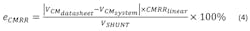
If the datasheet specifies CMRR in decibels, you will first need to convert this number to a linear value using Equation 5:

VCM (DATASHEET) is the common-mode voltage at which CMRR was tested; you will also find this listed in the device’s datasheet. VCM(SYSTEM) is the common-mode voltage that you will use in your implementation. For this example, let’s use the INA210 and assume that the system common-mode voltage is 15 V with the same 5 A and 1 mΩ. The CMRR spec is 105 dB at a common-mode voltage of 12 V. This will result in an error of 0.34%.
PSRR is a measure of the change in VOS created by the change in power-supply voltage. Its error contribution is calculated exactly like CMRR, replacing common-mode voltage with supply voltage (Equation 6):
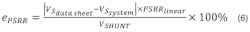
The INA210’s datasheet lists a PSRR of 10 µV/V at a supply voltage of 5 V. Using the shunt value of 1 mΩ with 5 A and assuming that the 5-V supply could be ±0.5 V, the error contribution would be 0.10%.
With each of these three offset error sources—VOS, CMRR, and PSRR—there’s an inverse relationship between VSHUNT and the error. As current decreases, resulting in lower VSHUNT, the error will increase proportionally. To decrease these errors, you have two options: increase the RSHUNT resistance or choose a device with improved specifications.
Increasing the RSHUNT resistance may or may not be feasible due to cost, board space, or power-dissipation requirements. Therefore, the best way to minimize such error contributions is to pick a device with as low a VOS as needed for minimum load-current conditions, as well as high levels of CMRR and PSRR.
When VSHUNT is much greater than VOS, it minimizes the contribution of offset error sources and the main error contribution will be the gain error. Most datasheets specify gain error as a flat percentage, and it’s a linear constant over the entire range of the device. The contribution is a straightforward percentage adder.
Total Error
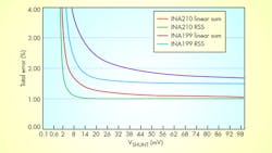
Now let’s see how these four amplifier-related error sources contribute to total error. The figure shows the linear sum as well as the root-sum-square method of error calculation for the INA199 and INA210.
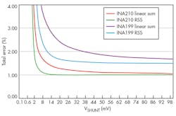
Offset errors dominate when VSHUNT is low and gain error dominates when VSHUNT is high relative to VOS.
The specifications will also have a temperature-drift effect. To calculate the error at a different temperature than room temperature, you can use the same equations, but first you must add the temperature-drift effect to the specification of interest. For example, the INA210 has a maximum VOS of 35 µV, but the datasheet only specifies this maximum at 25°C. The datasheet does list the ΔVOS/ΔT as a maximum of 0.5 µV/°C. Therefore, if the temperature of interest is 50°C, VOS could be as high as 47.5 µV. So the error contribution of the above example at a 5-mV VSHUNT goes from 0.7% to 0.95%.
Tradeoffs
As you work through this exercise for your application, it will quickly become apparent that tradeoffs will need to be made between precision and cost. Simply put, high-precision, low-drift components cost more than lower-performing alternatives, just like high-end, feature-rich cars cost more than basic sedans.
Now considering external error sources, implementing current measurement with a current-sense amplifier instead of a standard operational amplifier eliminates the error contribution of external discrete components. The device parameters factor in the error contribution of the integrated, matched, low-drift gain-resistor networks.
The VSHUNT that the amplifier sees is what exists across the input pins, which will be different than when measuring across the resistor. Ideally they would be the same, but parasitic effects and trace etch cause discrepancies. A Kelvin connection will minimize the PCB parasitic-error contribution. You should use standard PCB layout techniques to minimize error contribution caused by these layout effects.
This leaves the contributions of the shunt resistor itself. The datasheet for the shunt resistor will specify its tolerance and drift characteristics. The shunt tolerance will be a direct error addition, just like the gain error of the amplifier. A 5% shunt will add that amount of error into the total error.
Obviously, the shunt can very easily become a major error source, regardless of amplifier accuracy. Even more than the amplifier, with the shunt resistor you will have a tradeoff between the cost you are willing to pay and your application’s required performance. The shunt resistor’s temperature drift is one of the main error sources over temperature, unless you choose a costly resistor. High-precision (0.1%), low-drift (50 ppm/°C) resistors on catalog distribution sites cost somewhere between $4 and $8 in 1000-unit quantities.
Texas Instruments recently released the INA250 current-sense amplifier, which integrates a high-precision (0.1%), low-drift (15 ppm/°C) shunt resistor. When combined with the amplifier characteristics, the INA250 offers a maximum error of 0.75% with a drift of less than 50 ppm/°C. In addition, the integration ensures a Kelvin connection to minimize board-layout error-contribution factors. The Web-listed $1.40 price for 1000 units is a premium over amplifiers with similar performance parameters such as the INA210 ($0.75 for 1000 units). However, if you add in the cost of an external precision shunt resistor, you can quickly offset the additional cost of the integrated solution versus the discrete solution.
Current-measurement accuracy is a very complex subject that has many moving parts. You will need to make tradeoffs to maximize the performance for your specific operating conditions. Using devices with low-drift characteristics and high precision can help minimize error, but you must balance the achievable performance against the target cost for your solution.
About the Author
Dan Harmon
Marketing Manager, Current and Power Measurement Product Line
Dan Harmon is the marketing manager for the Current and Power Measurement Product Line at Texas Instruments. In his 30-year career at TI, he has supported a wide variety of technologies and products including interface products, imaging analog front-ends (AFEs), and charge-coupled device (CCD) sensors. He also has served as TI’s USB-IF representative and TI’s USB 3.0 Promoter’s Group Chairman. Dan earned a BSEE from the University of Dayton and a MSEE from the University of Texas in Arlington. He can be reached at [email protected].
Comment About the Article
To join the conversation, and become an exclusive member of Electronic Design, create an account today!

Leaders relevant to this article: