This file type includes high resolution graphics and schematics when applicable.
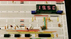
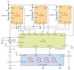
Applications such as healthcare or aerospace systems require high reliability when making basic measurements. By using a microcontroller as the “master” to perform majority-logic voting of measurements performed by three small independent microcontrollers, this circuit design provides a high-reliability thermometer based on triplicated modular redundancy (TMR) (Fig. 1). The TMR scheme is able to tolerate the failure of one MCU or associated thermistor sensor to provide a correct temperature reading from 0 to 100°C with a resolution of 0.1°C, while the master MCU discards the reading of the failed unit.
The reliability of each microcontroller module M is defined as:
R(t) = e–λt
where λ is the failure rate defined by the standard MIL-HBDK-217. Using the Reliability Analytics toolkit1, you can obtain λ for this specific device. The reliability for each PIC12F683 microcontroller in 1000 hours equals 0.9979 and is given by the formula:
R(t) = e–2.152t
The reliability for the voting microcontroller is 0.9978 in 1000 hours and is defined by:
R(t) = e–2.228t
while the total system reliability is given by:
where N is the number of modules, and M is the number of modules required for the system to survive (in this case, equal to 2). Therefore, total system reliability is defined by:
RTMR = e–2.228t (3e–4.304t – 2e–6.456t)
To get the most accurate temperature measurements using three equal but independent thermistors, use the Steinhart-Hart equation:2
1/T = a + b ln(R) + c (ln(R))3
Each PIC12F683 MCU (U1, U2, U3) reads a temperature with its own thermistor and solves the Steinhart-Hart equation (Listing 1). All four microcontrollers are synchronized with an external 4-MHz crystal connected to master microcontroller U4 (PIC16F88).
Listing 1: Software program for the small PICs (12F683)

@ include "12F683.inc"
@ __CONFIG _XT_OSC & _MCLRE_OFF;External Xtal oscillator, GPIO3 as digital input
; ALGORITHM FOR STEINHART-HART EQUATION By Ricardo Jimenez and Roberto Solorio
TRISIO=%00111100; I/O configuration
ANSEL=%00000100;    AN2 analog input
ADCON0=%10001010;    ADC configuration
OSCCON= %01101110;    Oscillator configuration
CMCON0 = %00000111;  Comparator configuration
define ADC_BITS 10;      Resolution of the A-to-D converter
DEFINE ADC_CLOCK 3;      ADC clock source
DEFINE SAMPLEUS 50;      50 uS sampling time
OSCTUNE=0;            osc tuning reg
volt var word;              declaring voltage as a var word
s var word: z var word: ma var word: h var word: y var word ;
w var word: r var word: ki var word: ln var word: ka var word: wu var word: ja var word;
zuyu var word: lna var word: lnb var word;
lnc var word:lna1 var word: dif var word;
aa var word; Coefficient a of Steinhart-Hart Eq.
bb var word; Coefficient b of Steinhart-Hart Eq.
cc var word;  Coefficient c of Steinhart-Hart Eq.
aa=2501;
bb=35050;
cc=1415;
lna1 =0;
volt=0;

XX:
IF GPIO.3=1 THEN GOTO X; Loop
GOTO XX

X:
; Clearing port and variables
GPIO=0;
z= 1;
s= 0;
ma= 0;
y= 0;
w= 0;
ki= 0;
r= 0;
ka= 0;
wu= 0;
ja= 0;
zuyu= 0;
dif= 0;
;**** reading thermistor’s resistance

ADCIN 2, volt;        Reading voltage on thermistor
volt = 48828 * volt ; 1024*4882=49,999,872; bin to dec conversion
volt= DIV32 10000 ;  thermistor’s voltage

;Voltage Division:
dif=5000-volt;     Power Supply Voltage minus thermistor’s voltaje drop
volt=volt*10000;   thermistor’s voltaje times fixed 10K resistor
r= DIV32 dif;  r= vf*r(vf-vt),  thermistor’s resistance equal to  Vcc times fixed R / (Vcc –Vth)

; *******Computing base 2 Logarithm
wu=(ncd r) -1;    finding the Logarithm’s characteristic
for s=0 to (wu-1);  loop to compute "ja" to find the manthisa
z=1;
if r.0=1 then;    if r has a 1,  bit 0 is odd, thus it will have a value for "ja"
for ki= (wu-s) to 1 step-1 ; loop to find  q in bit 0 for "ja"
z=z*2
next ki
ja=(10000/z)+ja;  the portion for "ja" depends on the division number performed by 2
endif
r=r/2; dividiing r by 2
next s

Mantisa:
ma=1000+(ja/10);   "fraction ja" is added the "integer"
z=1

; *************Computing the manthisa
for h=1 to 15 ; Creating a loop to compute the manthisa with 4 bits in  base 2
ma=ma*ma   ; raising "ma" to the square power
ma=div32 1000
z=z*2
if ma>2000 Then ;  comparison to 2000
y=y+(10000/z);  if it is greater than 2000, it will provide to the manthisa
ma=ma/2     ; Dividing ma by 2
endif
Next h
y=y/10;

; ************ Computing the Natural Log
ln=(wu*1000)+y;  Base 2 logarithm  is equal to the Characteristic plus the Manthisa
ln=ln*6931;        Changing base
ln= div32 10000;   multiplying by .6931 to obtain Natural Log

; Processing the Steinhart-Hart equation

lnc=ln*ln;
lnc=div32 10000;
lnc=ln*lnc;
lnc=div32 10000;
lnc=cc*lnc;
lnc=div32 10000;
lnb=ln*bb;
lnb=div32 10000;
lna=aa+lnb-lnc
lna=lna/10;

; Computing the denominator’s reciprocal

y=10000/lna;
lna1=10000//lna;
lna1=lna1*10;
w=lna1/lna;
lna1=lna1//lna;
lna1=lna1*10;
ka=lna1/lna;
lna1=lna1//lna;
lna1=lna1*10;
s=lna1/lna;
zuyu=(y*1000)+(w*100)+(ka*10)+s ; Summing the 4 coefficients assigning their respective weight
zuyu=zuyu-2730;                      Computing Temperature in C*10, Tf*10-2300

GPIO.1=1;    Serial Data Transfer of Temperature to the Master PIC 16F88
PAUSE 4;
GPIO.0=0;
GPIO.0=ZUYU.15;
PAUSE 10;
GPIO.0=ZUYU.14;
PAUSE 10;
GPIO.0=ZUYU.13;
PAUSE 10;
GPIO.0=ZUYU.12;
PAUSE 10;
GPIO.0=ZUYU.11;
PAUSE 10;
GPIO.0=ZUYU.10;
PAUSE 10;
GPIO.0=ZUYU.9;
PAUSE 10;
GPIO.0=ZUYU.8;
PAUSE 10;
GPIO.0=ZUYU.7;
PAUSE 10;
GPIO.0=ZUYU.6;
PAUSE 10;
GPIO.0=ZUYU.5;
PAUSE 10;
GPIO.0=ZUYU.4;
PAUSE 10;
GPIO.0=ZUYU.3;
PAUSE 10;
GPIO.0=ZUYU.2;
PAUSE 10;
GPIO.0=ZUYU.1;
PAUSE 10;
GPIO.0=ZUYU.0;
PAUSE 10;
GPIO.1=0;
PAUSE 725;
GOTO XX;
END
Listing 2 is the program for the majority voting, which serially receives the temperature data from each slave U1, U2, U3 (PIC12F683). The Steinhart-Hart algorithm was adapted for the PIC12F683 PICs, which use software-based serial communications to send the temperature data to the master microcontroller.
Listing 2: Software program for the master microcontroller (PIC 16F88) @ include "16F88.inc" @ __CONFIG _CONFIG1, _XT_OSC; External Xtal oscillator. TRISA=%10111111; I/O PORTA configuration TRISB=%00000010; I/O PORTB configuration ANSEL=0; Analog inputs off ADCON0=0; ADCON1=0; CMCON= %00000111; Comparator configuration OSCCON= %01100100; Oscillator configuration OSCTUNE=0; OSCILLATOR TUNING REGISTER T1 VAR WORD:T2 VAR WORD:T3 VAR WORD; P1 VAR WORD:P2 VAR WORD:P3 VAR WORD; C1 VAR WORD:C2 VAR WORD:C3 VAR WORD; TEMP VAR WORD:TEMP1 VAR WORD:TEMP2 VAR WORD; Aw VAR WORD:Bw VAR WORD:Cw VAR WORD:Dw VAR WORD:yi var byte::Fw VAR BYTE:ad VAR BYTE L VAR BYTE:E3 VAR BYTE:E1 VAR BYTE:E2 VAR BYTE pattern0 var byte:pattern1 var byte:pattern2 var byte:pattern3 var byte; b1 var bit:b2 var bit:b3 var bit:b4 var bit:b5 var bit:b6 var bit:b7 var bit: b8 var bit:b9 var bit:b10 var bit:b11 var bit:b12 var bit:b13 var bit:b14 var bit: b15 var bit:b16 VaR BIT q1 var bit:q2 var bit:q3 var bit:q4 var bit:q5 var bit:q6 var bit:q7 var bit: q8 var bit:q9 var bit:q10 var bit:q11 var bit:q12 var bit:q13 var bit:q14 var bit: q15 var bit:q16 VaR BIT z1 var bit:z2 var bit:z3 var bit:z4 var bit:z5 var bit:z6 var bit:z7 var bit: z8 var bit:z9 var bit:z10 var bit:z11 var bit:z12 var bit:z13 var bit:z14 var bit: z15 var bit:z16 VaR BIT XX: ; Clearing Variables PORTA=0:PORTB=0; Clear ports. Aw=0:Bw=0:Cw=0:Dw=0 ; b1=0:b2=0:b3=0:b4=0:b5=0:b6=0:b7=0:b8=0:b9=0:b10=0:b11=0:b12=0:b13=0:b14=0; b15=0:b16=0:q1=0:q2=0:q3=0:q4=0:q5=0:q6=0:q7=0:q8=0:q9=0:q10=0:q11=0:q12=0; q13=0:q14=0:q15=0:q16=0:z1=0:z2=0:z3=0:z4=0:z5=0:z6=0:z7=0:z8=0:z9=0:z10=0; z11=0:z12=0:z13=0:z14=0:z15=0:z16=0 ; pattern0=0:pattern1=0:pattern2=0:pattern3=0 ; C1=0:C2=0:C3=0 ; P1=0:P2=0:P3=0 ; T1=0:T2=0:T3=0 ; TEMP=0:TEMP1=0:TEMP2=0 ; Values of letters and numbers to show on display yi=%0111001; Value for C Fw=%1110001; Value for F AD=%1110111; Value for A L=%0111000; Value for L E1=%0000110; Value for 1 E2=%1011011; Value for 2 E3=%1001111; Value for 3 PORTB.0=1; Pulse to start the thermometers on each slave 12f683 IF PORTA.3=1 AND PORTA.4=1 AND PORTB.1=1 THEN GOSUB LECTURA; Serial in condition GOTO XX; ; Serial in routine LECTURA: b1=PORTA.1; q1=PORTA.0; z1=PORTA.2; pause 11; b2=PORTA.1; q2=PORTA.0; z2=PORTA.2; pause 11; b3=PORTA.1; q3=PORTA.0; z3=PORTA.2; pause 11; b4=PORTA.1; q4=PORTA.0; z4=PORTA.2; pause 11; b5=PORTA.1; q5=PORTA.0; z5=PORTA.2; pause 11; b6=PORTA.1; q6=PORTA.0; z6=PORTA.2; pause 11; b7=PORTA.1; q7=PORTA.0; z7=PORTA.2; pause 11; b8=PORTA.1; q8=PORTA.0; z8=PORTA.2; pause 11; b9=PORTA.1; q9=PORTA.0; z9=PORTA.2; pause 11; b10=PORTA.1; q10=PORTA.0; z10=PORTA.2; pause 11; b11=PORTA.1; q11=PORTA.0; z11=PORTA.2; pause 11; b12=PORTA.1; q12=PORTA.0; z12=PORTA.2; pause 11; b13=PORTA.1; q13=PORTA.0; z13=PORTA.2; pause 11; b14=PORTA.1; q14=PORTA.0; z14=PORTA.2; pause 11; b15=PORTA.1; q15=PORTA.0; z15=PORTA.2; pause 11; b16=PORTA.1; q16=PORTA.0; z16=PORTA.2; pause 11; T1.15=b1; T1.14=b2; T1.13=b3; T1.12=b4; T1.11=b5; T1.10=b6; T1.9=b7; T1.8=b8; T1.7=b9; T1.6=b10; T1.5=b11; T1.4=b12; T1.3=b13; T1.2=b14; T1.1=b15; T1.0=b16; T2.15=q1; T2.14=q2; T2.13=q3; T2.12=q4; T2.11=q5; T2.10=q6; T2.9=q7; T2.8=q8; T2.7=q9; T2.6=q10; T2.5=q11; T2.4=q12; T2.3=q13; T2.2=q14; T2.1=q15; T2.0=q16; T3.15=z1; T3.14=z2; T3.13=z3; T3.12=z4; T3.11=z5; T3.10=z6; T3.9=z7; T3.8=z8; T3.7=z9; T3.6=z10; T3.5=z11; T3.4=z12; T3.3=z13; T3.2=z14; T3.1=z15; T3.0=z16; PORTB.0=0; pause 5; ; Voting routine C1=t1-t2; C2=t2-t3; C3=t3-t1; P1=ABS C1; P2=ABS C2; P3=ABS C3; IF P1When the program starts, it will not run until GPIO.3 goes to logic 1. After meeting this condition, it will begin computing the temperature. When the process is complete, GPIO.1 will go to logic 1, and a small pause is inserted to start the transmission, which places the value of each bit of the variable that stores the temperature reading on GPIO.0. When finished, GPIO.1 goes to logic 0 for 725 ms to allow the voter to perform its process and display the data on the display. The program then will go to the main label.
The Voting microcontroller starts by setting PORTB.0 = 1, and this pulse starts the individual modules. Then, if PORTA.3, and PORTA.4, and PORTA.1 are equal to logic 1, it will start with the instructions. Each module generates this pulse before starting the transmission. When this condition is met for the serial input, the Voter continues with the instructions by reading the different ports on which the data enters, and stores it in different variable BITs. These will be the bits of the variable WORD where the final temperature will be stored. Once the serial communication is finished, the Voter proceeds to perform the following operations:
t1 – t2 = c1
t2 – t3 = c2
t3 – t1 = c3
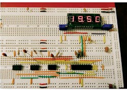
where c1, c2, and c3 represent the difference among the temperature readings. The instruction ABS is used to get the absolute values of these differences. The smallest difference between two temperatures means that these are the most precise readings, which are then averaged and displayed (Fig. 2). The module that provides a major difference will be discarded, and the display (Lite-On LTM-8328PKR-04) will indicate which module has failed.
When choosing what temperatures should be averaged, a process is followed to make sure that their difference is the smallest one. Then the instruction DIG stores each decimal digit of the temperature, and the instruction LOOKUP makes the conversion to a seven-segment format. The formatted data will be serially transmitted and synchronized with a clock signal generated by the microcontroller. A redundant 5-V dc power supply is recommended to ensure high reliability in this design.
This file type includes high resolution graphics and schematics when applicable.
References:
1. Reliability Analytics Toolkit
2. R. Jimenez and R. Solorio, “Microcontroller Solves Complex Temperature Polynomial Equations” Electronic Design, December 5, 2013.
Ricardo Jimenez-Garcia holds a Master’s in electronics from Instituto Tecnológico de Mexicali (ITM), (Mexicali, BC, Mexico) and an electronics engineering degree from Instituto Tecnológico de Durango (Durango, Mexico). He is an adjunct professor at Imperial Valley College, Imperial, Calif., and at ITT Tech, Vista, Calif. He can be reached at [email protected].
Gerardo Velasco-Equihua is a student in electronics engineering at ITM.


