Oscilloscope Triggering Advanced Course: Advanced Trigger Modes, Part 2
This file type includes high-resolution graphics and schematics when applicable.
Welcome to the Oscilloscope Triggering Advanced Course! In this series, I will walk you through the details of every corner of real-time oscilloscope trigger systems, and by the time we’re done, you’ll never need that AutoScale button again! Your co-workers will be stuck in the lab staring at auto-triggers all weekend while your scope is catching glitches and protocol packets automagically and emailing you the results!
We’re going to start off by talking about advanced trigger modes. These are the different operational modes you choose first when setting up your trigger, with each mode having different options. Broadly speaking, most advanced trigger modes fall into three categories—pulse modes, pattern modes, and edge modes—and we’ll discuss each in detail. Part 1 focused on pulse and pattern modes. In Part 2, I’ll focus on advanced edge-based trigger modes as well as a few other common advanced modes that don’t really fall into any of the other categories. Ready to get started?
Edge Modes
Unlike pulse- and pattern-based modes, which are fairly standardized, edge-based trigger modes are a little tougher to cover in-depth because they differ quite a bit from scope to scope. In general, advanced edge-based trigger modes fall into three categories:
• Single edge
• Timed edge
• N-edge
The names and available input parameters for these modes vary significantly from scope to scope, as does their availability in general. I’ll discuss each category briefly and provide a few examples.
Single edge
So, I know what you’re thinking—regular old edge trigger is hardly “advanced”—and you’re absolutely right. However, a few options for single-edge trigger modes on newer scopes provide advanced functionality worth mentioning here:
• Either/alternating edge: Typically selected as an option when setting up regular edge trigger, either/alternating-edge functionality allows you to specify that the scope should trigger on either edge (rising or falling), or that it should alternate between edge polarities for each trigger event (e.g., rising/falling/rising/falling, etc.). Either edge mode can be handy when you don’t really know what the signal is going to do, but you want to make sure you catch it. Alternating edge mode is useful for looking at rising and falling transitions plotted on top of each other (it’s also used under-the-covers to plot real-time eye diagrams!).
• OR’d edges: Often simply called “OR” mode, this mode allows users to specify different edge polarities on different input channels and trigger whenever there’s an occurrence of any of these events. I classify this as a single-edge trigger because even though the user may specify many inputs, only one of those inputs generates a particular trigger event.
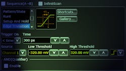
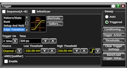
Timed edge
Of all the advanced edge-based modes, timed edge, also referred to as “edge transition,” “risetime,” and “slew rate,” is the most common across different scope models. The user specifies an input channel, an edge polarity, two vertical thresholds, at least one time parameter, and a parameter that defines how the measured edge transition time should be compared with the input time parameter(s). This mode is actually quite similar to pulse-width mode, but instead of applying the time comparison to a pulse width, we’re applying it to an edge transition time.
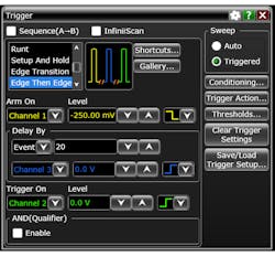
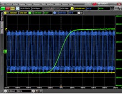
N-edge
This is where things get a bit confusing. Most newer oscilloscope models provide at least one trigger mode based on the idea of counting multiple edges. The names of these modes, their features, and available configurations vary significantly from scope to scope. In general, these modes typically have an “arm” event followed by a “trigger” event. They may also have an intermediate delay event in between the arm and trigger events. This probably sounds familiar to those accustomed to trigger sequences (we’ll talk about trigger sequences in depth in a later article). Various scopes refer to these trigger modes as “edge-then-edge,” “nth edge,” “interval,” “dropout,” etc.
Other Advanced Modes
Two fairly common advanced trigger modes don’t cleanly fall into any of the above categories: timeout and window.
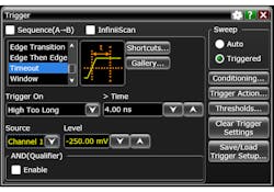
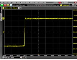
Timeout mode
Timeout trigger mode is similar to pulse-width mode, with the greater-than time condition locked in. The main difference is that with timeout, a trigger will be generated after an edge is detected, when no other transition is detected for a duration of time greater than a time parameter (the “timeout” time). The user specifies the input channel, vertical threshold, polarity (“high-too-long,” “low-too-long,” etc.), and time parameter.
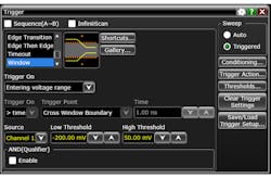
Window mode
Window mode, like pattern mode, is somewhat of a “super mode”—in some scopes, it can encompass many different variants. The general idea with window mode is that the user specifies an input channel and two vertical thresholds. The area between the two thresholds is the “window.” Depending on the scope, the user will be able to choose to trigger when the signal “enters” the window (when it transitions from outside the region bounded by the thresholds to inside it), exits the window, or is inside or outside the window for greater or less than a specified amount of time.
Conclusion
By now you probably think you know all there is to know about oscilloscope triggering. However, this review of common advanced trigger modes really only scratches the surface. In the next article, we’ll dive into protocol triggering. Stay tuned!

About the Author
Colin Mattson
R&D Engineer
Colin F. Mattson is an engineer in Research & Development at Keysight Technologies in Colorado. Focusing on real-time oscilloscope trigger systems, Colin has been with Agilent/Keysight since early 2013. He received his BSEE/CE from Oakland University in 2012.
Comment About the Article
To join the conversation, and become an exclusive member of Electronic Design, create an account today!

Leaders relevant to this article: