Oscilloscope Triggering Advanced Course: Trigger Sequencing and Software Search Triggers
Download this article in PDF format.
Welcome to the Oscilloscope Triggering Advanced Course! In this series, I will walk you through the details of every corner of real-time oscilloscope trigger systems, and by the time we’re done, you’ll never need that AutoScale button again! Your co-workers will be stuck in the lab staring at auto-triggers all weekend while your scope is catching glitches and protocol packets automagically and emailing you the results. If you’re just joining us now, do yourself a favor and also check out the first three articles in the series to learn about advanced trigger modes and protocol triggering.
In this article, we’re going to dive head-first into two of the most commonly misunderstood advanced trigger features in modern oscilloscopes: trigger sequencing and software search triggers.
Trigger Sequencing
A trigger sequence is a trigger configuration that requires n events to occur in a specified order (the “sequence”) in order for a trigger to occur. Each event in the sequence is referred to as a “stage.” The final event in the sequence is referred to as the “trigger” event and all preceding events are referred to as “arm” events. Most scopes that support sequence triggering only offer two sequence stages; Figure 1 shows the simplest trigger sequence.
However, some scopes offer more than two stages for sequence triggering. Figure 2 more accurately represents a generalized trigger sequence. Because most scopes that support sequence triggering only offer two stages and often label those stages “A” and “B,” sequence triggering is sometimes referred to as “A/B triggering.”
So why would you want to use a trigger sequence? The simple answer is that you’re interested in capturing behavior that happens after other specific events occur in a specific order. If we think back on our discussion of advanced trigger modes (the first two articles in this series), we can configure a trigger mode to look for all kinds of behavior—edge transition times, pulse widths, setup-and-hold violations, etc. But all of these trigger modes look for a single condition to be true at a single instant in time.
Granted, such a condition can get very complex and it may be evaluated over a range of time (i.e., pattern range trigger). However, trigger modes don’t have the concept of a number of different events happening in a particular order. (Note: there are a few count-based trigger modes that evaluate multiple occurrences of the same event.)
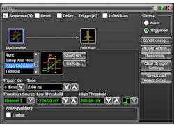
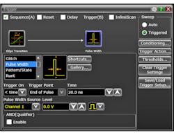
Let’s set up a sequence to arm on a rising edge that takes more than 2 ns to transition on channel 2, and trigger on a pulse width that’s less than 20 ns on channel 1 (Figs. 3 and 4). The setup for these two stages will be presented differently on different scopes. For our examples, we’ll be using a Keysight Infiniium S-Series scope, which offers up to two sequence stages (similar to the diagram in Fig. 1) and presents the setup for each stage separately. The user selects which stage to configure by selecting it in the Trigger setup dialog.
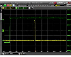
Note that the trigger point for any trigger sequence is always the trigger point for the event configured in the final stage. In this example, the final stage is configured as “pulse width less than 20 ns” and the trigger point is set as “end of pulse,” which is exactly what we see at t = 0.0s onscreen (Fig. 5).
Advanced Sequence Features: Reset and Delay
In addition to the simple arm-then-trigger sequence, some scopes will allow the user to configure special events in between the stages of a sequence. These features enable the user to not only specify the order of multiple events, but also the time between them, as well as indicate what to do should that time condition be violated. The availability of these features, their limits, and the specifics of their functionality will vary significantly across different scope models.
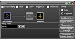
Sequence delay is a simple timer that can be inserted between sequence stages. Essentially, sequence delay is an additional arm stage—after the preceding arm stage is satisfied (its configured event is detected), the sequence delay timer will start and the following stage will not be armed until the timer completes. Let’s add a 65-ns delay to the trigger sequence we configured earlier as an example (Fig. 6).
Sequence reset is a powerful feature that basically allows the user to specify when to ignore an arm event. When reset is enabled, if the configured reset event occurs after the arm stage is satisfied, but before the trigger stage event is detected, the reset block will disarm the trigger stage and reset the arm stage. Essentially, then, it will ignore the first arm event. Two common types of events can be configured as a reset:
• Time: Like sequence delay, reset-by-time is a timer inserted between two sequence stages that starts as soon as the preceding stage is satisfied. If the reset timer completes before the following stage is satisfied, a reset will occur, disarming the following stage and resetting the preceding stage.
• Events: Reset-by-event allows the user to reset the trigger sequence when a configured input signal goes high or low relative to a threshold.
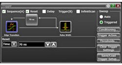
Let’s configure two different types of sequence reset and add them to our original trigger sequence configuration. We’ll start with reset-by-time at 70 ns (Fig. 7).
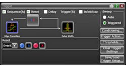
Next, let’s setup for reset-by-events and configure our reset event as Channel 3 going high (Fig. 8). Note that when we say a signal is “high” or “low,” we’re referring to its position relative to its threshold.
It’s possible in some scopes to use sequence reset and delay simultaneously, but the order in which these will be executed (i.e., does the delay occur before or after the reset?) varies from scope to scope. So, if you want to setup a trigger that uses both, make sure you understand how your scope implements these features.
Software Search Triggers
Software search triggering is one of the most powerful features available on modern scopes, but it carries a unique set of limitations that are important to understand. What exactly is a search trigger? The answer is that it isn’t really a trigger at all in the traditional sense. With normal hardware (analog or digital) triggers, the qualification of the trigger event is completely asynchronous to acquisition. Note: while hardware triggers are asynchronous to acquisition, they are still gated (armed/disarmed) by the scope acquisition cycle!
This means that the trigger system can analyze millions of potential trigger events without the scope ever acquiring any digital data. In this scenario, the trigger is armed by the acquisition system immediately following the previous acquisition, and it stays armed until it finds a valid trigger event and fires. While the trigger system is armed, the dead time between finishing the analysis of one potential trigger event and being able to begin analyzing another potential trigger event is very small. Thus, it’s unlikely you could miss the trigger you’re looking for.
Search triggers essentially build an extra layer of analysis on top of the hardware system. First, a hardware trigger is configured (either explicitly by the user or under the hood by scope software). Then, for every hardware trigger that occurs, the scope acquires data and subsequently runs an algorithm to decide whether or not the acquired data passes or fails the configured search trigger conditions.
If the data passes, it’s considered a valid trigger event and data is plotted to the screen for viewing/measurement, etc., just like a regular old hardware trigger. If it fails, the data is discarded and never made available to the rest of the system, the hardware trigger is re-armed, and the cycle starts over. The important thing to note here is that search triggers operate on acquired data. If the hardware trigger fires and starts an acquisition, it won’t be able to re-arm again until after the acquisition and analysis are finished, which increases the probability of missing a valid trigger event.
So why would anyone want to use a search trigger if they have a higher probability of missing valid trigger events? Because the search algorithms have access to the complete acquired waveform data, and thus can provide extremely powerful analysis capability that isn’t available in the hardware trigger system.
Search triggers can be configured to look for all kinds of different things: measurement results that exceed certain bounds, protocol packets with certain data, etc. Regarding protocols, not all protocol triggers are search triggers. See my last article in this series for a deep dive on hardware protocol triggering. Search triggers are a convenient way for scope manufacturers to support protocol triggering on frames that lack dedicated hardware.
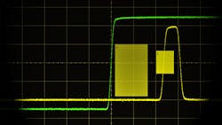
Let’s look at an example using my personal favorite search trigger: the zone trigger. Zone triggering is one flavor of search trigger where the user arbitrarily defines a number of different two-dimensional zones on the scope screen, each one relative to a signal. For each zone, the user specifies that particular signal must intersect that zone or must not intersect that zone. If you’re familiar with the “mask test” feature on many scopes, you can think of zone trigger as super mask test applied to the trigger system.
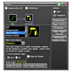
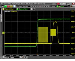
As an example, let’s set up a zone trigger as follows: rising edge trigger on Channel 2 as the hardware trigger followed by zone analysis on Channel 1 with two different zones (Fig. 9). The results of this configuration are shown in Figure 10. The trigger correctly captured the event we were looking for; Channel 1 is intersecting zone 1 and is not intersecting zone 2.
So when should one consider using a search trigger? The ideal case for a search trigger is anytime you need complex analysis capability above and beyond that offered by the hardware trigger system AND the event that will fire the hardware trigger prior to software analysis is fairly infrequent. The latter allows plenty of time for acquisition and analysis between potential trigger events.
That wraps up our discussion of trigger sequencing and software search triggers. Stay tuned for the next article in the Oscilloscope Triggering Advanced Course, in which we’ll discuss advanced trigger features!
About the Author
Colin Mattson
R&D Engineer
Colin F. Mattson is an engineer in Research & Development at Keysight Technologies in Colorado. Focusing on real-time oscilloscope trigger systems, Colin has been with Agilent/Keysight since early 2013. He received his BSEE/CE from Oakland University in 2012.
