Prevent Overcharging of Li-Ion Cells
Download this article in PDF format.
Over the years, serious concerns have emerged about lithium-ion cell safety. There have been factory fires, mobile phones and laptop computers bursting into flames, and even the grounding of a 787 aircraft. So, when forming or charging Li-ion cells in manufacturing or during characterization in R&D, special attention must be paid to prevent dangerous conditions that can lead to those cell fires.
One key area of concern is applying overvoltage or overcharging during charging. If the charging voltage is increased beyond the recommended upper cell voltage or if the cell is overcharged, lithium ions can build up on the anode as metallic lithium, which is called lithium plating. The plating can occur as dendrites inside the cell, which could ultimately result in a short circuit between the electrodes. The short circuit can increase the internal cell temperature, which may lead to thermal runaway that results in damaged cells and possibly fire.
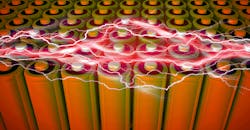
When developing a proper setup for cell charging or cell test, the electronics are connected to the cells via some form of contact or probe. For cells in a hard case, like a cylindrical or prismatic, the charger’s contacts are typically a pin-type probe. For pouch cells, where the cell uses tabs as electrical terminals, the charger’s contacts are usually some form of grabber or clips (Fig. 1).

1. Cylindrical cells (upper right) have a hard case, permitting use of pins for electrical contact to the cell during test. Pouch cells (left) have metal tabs, requiring clips or grippers to make electrical contact during test.
To maintain the highest voltage-regulation accuracy and control when large current is flowing into/out of the cell, it’s best to use a four-wire system called remote sensing. By remote sensing, the cell-charging electronics can adjust output voltage to compensate for the voltage drop in the power leads, even as the current changes.
For remote sensing to work, the cell charger has four output terminals. The “+” and “−” terminals are the charger output terminals to which the power leads are attached and through which high currents will flow into the cell. Sometimes these are referred to as the force terminals. As current flows through the power leads, there will be voltage drops through the resistance in the leads.
The other two terminals are the sense terminals, typically labeled “+S” and “−S.” The wires connected to them are called the sense leads (Fig. 2). The sense terminals are measurement terminals and therefore have high input impedance, so no current will flow into them. Since no current flows into the sense terminals, no current will flow through the sense leads. If no current is flowing, regardless of the resistance or the gauge of the sense wires, there will be no voltage drop in the sense leads. Thin wire, such as 18 or 22 gauge, can be used.
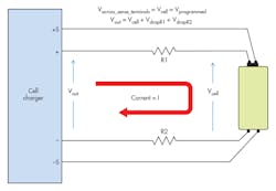
Therefore, regardless of the current flowing through the power leads, the voltage at the cell (Vcell) will appear at the sense terminals (Vacross_sense_terminals), allowing the charger to sense the actual voltage at the cell. Because this is a four-wire system, the charger regulates the voltage at the output terminals (Vout) to keep the voltage at the sense terminals exactly at the desired programmed value (Vprogrammed)—even if the voltage drops through the power leads (VdropR1, VdropR2) change during current changes. Because the voltage is maintained exactly at the desired programmed value, there’s no occurrence of an overvoltage condition on the cell. For more information on remote sensing, please see my previous article.
Remote Sensing Prevents Overvoltage, But…
Remote sensing with a four-wire connection ensures the voltage on the cell will be maintained carefully, as the sense wires provide a voltage-regulation feedback system to the charger that permits the charger to regulate voltage accurately. Thus, no overvoltage can be applied and there’s no overcharging. Remote sensing also means four probes will be in contact with the cell. This raises the concern about probe failures, as more probes and associated wires mean more possible failures. Let’s look at the effects of different types of probe failures.
Worst-Case Scenario: Sense Probe Failure
A sense probe failure on +S or −S can lead to accidental application of overvoltage during charge because the sense probe provides voltage-regulation feedback. Without proper feedback (sensing) of voltage, proper voltage regulation can’t be maintained and too much voltage may be applied to the cell, creating a potentially hazardous condition when the sense probes fail.
Power Probe Failure
If the power probe fails, then current can’t flow into the cell and it will not fully charge. Although undesirable, this isn’t harmful. A capacity test can identify if the cell hasn’t charged properly by comparing the actual amp-hours of energy put into the cell during charge with the expected amp-hours of charge. If too little energy is put into the cell, then the capacity test will flag the cell as “bad.” While the capacity test can’t distinguish between a good cell connected via bad probes or a bad cell connected via good probes, the capacity test will flag the cell as bad in either case. That’s because you were unable to reach the desired amp-hours of charge energy in the proper amount of time.
Solution: Probe Check
While a four-wire system has exceptional benefits, using more probes means that there’s greater potential for probe failure. As a result, a well-designed charger will include probe-check functions. The application of overvoltage is the most hazardous condition, since it can lead to fire, so the most basic level of probe check should detect sense probe failures.
A simple method to implement a sense probe check is to detect if there’s a difference between the voltage measured on the sense lines and the voltage on the power lines. This difference will occur upon failure of a sense probe. When the charger detects this voltage difference, the charger should flag the condition as a probe failure and stop charging the cell. This provides a base level of protection against overvoltage due to probe failures, but it doesn’t identify which probe (+S or -S) has failed.
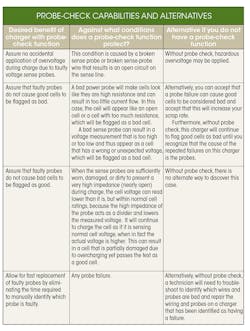
Beyond this basic probe-check method, other more advanced and sophisticated methods can be deployed. One more advanced probe check involves sensing the resistance of the probes and even automatically detecting which of the four probes has failed. Of course, adding more sophistication to the charger increases the cost and complexity. The table above summarizes the various probe-check capabilities (for a four-wire system) and alternatives if no or limited probe-check capability is deployed.

About the Author

Bob Zollo
Solution Architect for Battery Testing, Electronic Industrial Solutions Group
Bob Zollo is solution architect for battery testing for energy and automotive solutions in the Electronic Industrial Solutions Group of Keysight Technologies. Bob has been with Keysight since 1984 and holds a degree in electrical engineering from Stevens Institute of Technology, Hoboken, N.J. He can be contacted at [email protected].
Comment About the Article
To join the conversation, and become an exclusive member of Electronic Design, create an account today!

Leaders relevant to this article: