Shaken, Not Stirred—The Piezoelectric Effect and Oscilloscopes
Download this article in PDF format.
Here’s some advice from an oscilloscope expert: Don’t hit your oscilloscope while making measurements (and preferably not ever). It seems like this should go without saying, right? But in late March, the electrical engineering community (and consequently my inbox) was abuzz. The well-known electronics YouTuber Dave Jones posted “EEVBlog #983 – A Shocking Oscilloscope Problem”:
1. Here’s a simplified example of how charges move, causing the piezoelectric effect.
The Piezoelectric Effect and Oscilloscopes
So, what does the piezoelectric effect have to do with oscilloscopes? Try this and see for yourself:
1. Connect a standard passive probe to your oscilloscope.
2. Vertically zoom in on your signal to a small voltage per division setting.
3. Set the trigger level slightly above the baseline signal.
4. Remove the probe’s grabber hat and tap the exposed probe tip on a hard surface.
5. Don’t panic and always carry a towel.
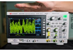
You should then see a signal that looks something like Figure 2. Remember, you may have to put your oscilloscope into “Normal” trigger mode to keep the signal on the screen. Alternatively, you can probably skip the probe altogether and simply tap on a bare BNC or even the top of the chassis. Now, don’t panic, this is something that occurs with every scope in existence.
2. A hand-numbingly hard slap to the top of the Keysight InfiniiVision 1000 X-Series Oscilloscope shows the piezoelectric effect of the acquisition board’s capacitors.
A signal is showing up on the oscilloscope because designers use ceramic capacitors in both probes and oscilloscope acquisition boards. Ceramic is a piezoelectric material, and the vibrations caused by physical force you exert on your probe and/or scope cause the capacitors to physically expand and contract slightly. This expansion and contraction creates an electric potential in the capacitors. Because these capacitors are part of the oscilloscope’s acquisition system, that potential shows up on the oscilloscope screen as a signal.
“So… (you ask me once you’re done hyperventilating), have all of my measurements been bogus up to this point? Can I minimize this effect? Is this something I should worry about?”
No, yes, and probably not.
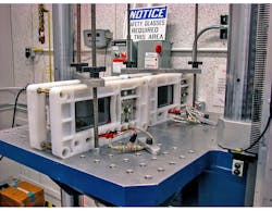
Unless you are working in the middle of a city-destroying earthquake or on the back of a kangaroo, you probably don’t have anything to worry about. Keysight oscilloscopes all go through extensive environmental and stress testing, including drop tests (up to 30 g) and time on a vibration table (Fig. 3). So, for Keysight oscilloscopes you can be confident that every-day vibrations won’t affect your measurements (but I can’t speak for other manufacturer’s testing procedures). If you’re concerned about this effect or work on the back of a kangaroo, try using an equipment cart or table that has built-in suspension (or maybe a towel…).
3. When testing for vibration, a table like this one is a better bet for good results than, say, using a towel.
To measure the effect of the piezoelectric effect on your systems, first make a baseline noise measurement in a stable environment (AC VRMS), and then make a baseline noise measurement in your testing environment. The difference in measurements will be due to both EMI and the piezoelectric effect. Ideally, this measurement should be made in an identical EMI-inducing environment to isolate piezoelectric effects. Side tip: You can also do this same thing to measure probe loading on your device.
Who Uses the Piezoelectric Effect?
You probably come across practical uses for the piezoelectric effect more often than you realize. For example, many acoustic instruments use piezoelectric pickups for sound amplification. Also, ultrasound machines and old-school apartment buzzer/intercoms rely on the piezoelectric effect for both signal generation and acquisition of signals.
Virtually all modern oscilloscopes use ceramic capacitors as part of their front-end acquisition blocks and various other parts of the printed-circuit board. Therefore, you see a signal on your oscilloscope when you tap or thump the top of your oscilloscope or a bare BNC. Passive probes can also have ceramic capacitors built into the probe tip and/or probe base, which is why tapping a probe on a tabletop or hard surface causes signals to appear on the screen.
Why Use Ceramic Capacitors if They’re Piezoelectric?
Ceramic capacitors have a few benefits over electrolytic capacitors. The most notable is that electrolytic capacitors have a much higher failure rate than their ceramic counterparts, so using ceramic capacitors makes oscilloscopes much more reliable. Ceramic caps, however, don’t work very well as the capacitance value increases. Ceramic capacitors max out at roughly 100 µF, although that’s a loose rule. This is why electrolytic capacitors are often used for power supplies.
Ceramic capacitors also have a lower equivalent series resistance (ESR) than electrolytic capacitors, which commonly leads to voltage ripples in a device. Obviously, the lower the ripple in an oscilloscope acquisition system, the cleaner the acquisition.
Electrolytic capacitors also change significantly as temperature changes. For an acquisition system, it’s crucial to have stable impedances to make sure that the oscilloscope adheres to its specification.
Finally, ceramic capacitors are much cheaper than electrolytic capacitors, so engineers concerned with reducing board costs often turn to ceramics.
Mind the Bumps
Even though using ceramic capacitors in oscilloscopes can have piezoelectric side effects under certain situations, the benefits of ceramics significantly outweigh the cons. The driving goal behind oscilloscope design is accurate acquisition and display of signals. Electrolytic capacitors induce undesirable uncertainty into acquisition systems, so we use ceramic capacitors.
If you need to make low noise measurements in high impedance mode and are in a physically rough environment, consider using some sort of shock-absorbing cart or table to lessen the vibrations. Otherwise, you have nothing to worry about.
Happy testing!
About the Author

Daniel Bogdanoff
Oscilloscope Product Manager
Daniel Bogdanoff is the Product Manager for the InfiniiVision series of oscilloscopes at Keysight Technologies. He graduated from Texas A&M with a degree in electrical engineering. In his spare time, Daniel enjoys whitewater kayaking, mountain biking and playing various musical instruments.


