Download this article in .PDF format
Efficiency in power-related systems is typically defined in terms of the useful power output divided by the total power consumed, as in "the efficiency of such-and-such switching power supply is 97%." Reliability in this case might be expressed as the mean time between failure (MBTF) of components.
1. "Are you sure I'm standing right next to the fuse box?" (Courtesy of Daily Mail)
TCO encompasses maintenance, service, and even migration costs at end of life (EOL). One factor that can escalate those numbers is the high cost of downtime once a product is in the field. Therefore, modifying a design to reduce the chance of a service call usually becomes the smart move.
Protection Circuitry—A Better Way
When it comes to protection circuitry, a long-used standard technique is to include a fuse to protect against an overcurrent condition. However, if the fuse blows, it must be replaced, perhaps at considerable expense if the product is in a remote location. Plus a blown fuse provides no information on the conditions leading up to the failure.
Luckily, there’s a more sophisticated approach to protection circuitry. Monitoring the current in real time with an analog front end and a microcontroller, and taking remedial action in advance of an actual failure, can maximize equipment uptime. Since powerful microcontrollers are already a key part of just about every design, it might even be possible to use an existing device.
Applications For Current Monitoring
Current monitoring is already an important component of numerous applications. In the automotive field, battery-management systems (BMSs) continually monitor battery-current usage patterns with a technique called coloumb counting. Over time, the BMS builds up a model of key battery parameters, such as state of charge (SoC) and state of health (SoH), to predict battery failure and allow the use of fuel-saving measures like stop-start control.
In consumer electronics, knowledge of current consumption in cell phones or tablets is key to measuring remaining battery life or effiiciently charging Li-ion battery stacks. And in industrial motor control, knowing the magnitude and direction of the current provides information about the speed and direction of the motor.
Solar power, battery-backup systems, and medical electronics are three other areas where accurate current monitoring plays a key role.
Shunt-Resistor Technology
A shunt resistor is the sensing element for most of these aforementioned applications. Choices abound for this device, depending on the application.
In regard to PCB mounting, shunt resistors are differentiated by value, temperature coefficient, power rating, and size. Cost is typically greater for lower TCR, higher power rating, and higher accuracy. Various manufacturing technologies can be employed, but a resistor made of nickel-chromium (NiCr) foil attached to a ceramic substrate has superior stability compared to thin- or thick-film technology.
For high-current precision applications like automotive battery management, specialized shunt resistors are available (Fig. 2). This resistor, inserted between the battery negative terminal and vehicle ground, is made from a proprietary copper-manganese-tin alloy with a high power rating and very low temperature coefficient of resistance (TCR).
Other Measurement Techniques
Although we'll concentrate on shunt resistor-based approaches in this article, they aren't the only game in town.
When measuring very high dc currents (in the 10-kA range), another option is a fiber-optic current sensor (FOCS). The FOCS makes use of the Faraday effect, which describes the interaction between light and a magnetic field that results in a rotation of polarized light proportionate to the magnetic-field strength. A typical arrangement uses an optical phase-detection circuit to measure the phase shift along an optical fiber encircling the conductor.
Sensing current in ac power lines presents its own set of problems, since both the current and voltage continuously change polarity. Transformer coupling of signals to drive ground-referenced circuitry is one solution, with the output being fed into an RMS-to-dc converter.
Current-Sensing Basics
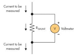
The basic principle of current measurement using a shunt resistor (Fig. 3) makes use of our old friend Ohm's Law. The current to be measured passes through a shunt resistor; the voltage drop across the resistor is measured by a voltmeter, and the current is calculated from:
I = V/RSHUNT
In an ideal world, it would be that simple. In the real world, though, our problems have just begun. First of all, the current through the shunt resistor isn’t static. It has a minimum and maximum value that together constitutes a dynamic range. In some cases, that dynamic range can be very large—the current from an automotive battery can vary from 100 μA to 2000 A. Whatever the range, it must be taken into account in gain calculations.
The shunt resistor dissipates power, which is given by:
P = V × I = V2/RSHUNT = I2 × RSHUNT
This power causes a rise in the resistor’s temperature due to Joule heating. The temperature rise changes the resistor value according to its TCR, leading to an error.
To curtail this error, designers try to minimize the voltage drop across the shunt resistor. However, a small voltage drop gives a small differential signal at the input stage of the measurement circuitry. Then the input amplifier’s offset voltage can become a significant source of error. Low input offsets are critical to achieving accurate measurements at the low end of the dynamic range.
At the other end of the scale—a large differential input—the error is dominated by the amplifier’s gain error. These errors can be significant: With a differential input voltage of 30 mV, a general-purpose op amp with a maximum offset voltage of 1 mV and a gain error of 5% can result in a total error of 6%.
Go here for a discussion of the various op-amp specifications.
High-Side vs. Low-Side Sensing
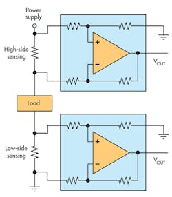
One of the first choices to be made is whether to measure the current between the power supply and the load (high-side sensing), or between the load and ground (low-side sensing). Figure 4 shows the two options. Each method has advantages and disadvantages (you knew that, didn't you?).
Low-side sensing has the advantage of simplicity and low cost since it typically only requires an op amp. On the other hand, the shunt resistance adds an undesirable resistance in the ground path. A low-side sensor can’t detect fault conditions caused by an open or short circuit on the low side of the load, and a simple op-amp circuit requires expensive precision components to achieve high accuracy.
High-side sensing doesn't introduce any ground disturbances. Still, it’s difficult to use a standard op amp without exceeding the common-mode range, which may extend well beyond the op amp's supply voltage. An op amp must also use precisely matched resistors to obtain acceptable common-mode rejection ratios (CMRRs).
In general, a low-side solution is preferable if the system can handle variations in the ground path. If that's not an option, or if the system must detect shorts to ground, go with a high-side solution.
We'll discuss design options for current sensing in the next few sections.
Op-Amp-Based Solution
Before the advent of specialized current-sensing devices, an overcurrent detection solution typically used a simple operational amplifier, external gain-setting resistors, and a low-cost comparator. The op amp and external gain-setting resistors form a difference amplifier to amplify the differential voltage across the shunt resistor and create a single-ended output voltage that’s routed to the comparator.
The comparator threshold is set to equal the output-voltage level of the current-sense amplifier corresponding to the required current level.
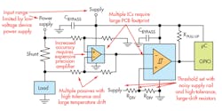
The reference circuitry depends on the required accuracy and stability. For lowest cost (and lowest accuracy), the reference signal can be a simple resistor-divider network; a high-end solution can employ a precision low-drift voltage reference. Low-cost operational amplifiers can be used, but will require expensive precision components for best performance.
Figure 5 shows some of the pitfalls that await.
Current-Sense Amplifier Plus Comparator
For a more accurate solution, we can replace the general-purpose op amp with a dedicated current-sense amplifier. Fabricating the op amp and the four gain-setting resistors on a single die provides much more precise operation and better TCR matching than a discrete solution, as well as reduces board space.
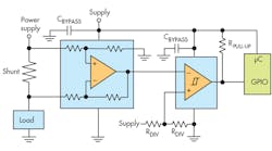
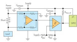
As shown in Figure 6, the current-sense amplifier’s output drives a comparator that trips when the current exceeds a preset threshold and alerts a microcontroller via a general-purpose I/O (GPIO) port. For a smaller footprint, the microcontroller can also read the current-sense amplifier output directly via an analog-to-digital input. Another option is to use a built-in comparator, if it’s available.
Again, the reference signal circuitry can run the gamut from a resistor-divider network to a precision voltage reference.
Single-Chip Solution
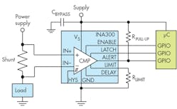
A dedicated current-sensing comparator is optimized for detecting overcurrent conditions (Fig. 7). It combines the precision measurement front end and comparator in a single-chip solution.
The INA300 is an example of such a device. It features an adjustable overcurrent threshold set by an external resistor. The response time is adjustable, enabling overcurrent alerts to be issued from 10 to 100 µs. The output can operate in one of two modes. In a transparent mode, the output status follows the input state. In a latched mode, the alert output is reset when the latch is cleared by the microcontroller, indicating that the overcurrent alert has been received.
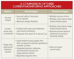
Overall, how do the various current-monitoring options stack up? The table summarizes their advantages and disadvantages.
Conclusion
Current measurement plays an important role in many systems, from automotive battery management to industrial motor control. A range of options extends this technique to provide protection against out-of-range conditions such as ground faults, short circuits, and overcurrent events.
Using the techniques described above, designers can diagnose faults and take remedial action in advance of a failure. Removing a fuse from the design can also eliminate downtime and reduce TCO.
