Download this article in PDF format.
The Complutense University of Madrid (UCM) is the biggest university in Spain and one of the oldest in Europe (founded in 1293), noted for its long tradition in science and humanities. However, in Spain, engineering degrees were usually taught at polytechnic schools. Then, the Bologna Process went into effect, which opened the door to many new and different degrees.
At UCM, we have an Informatics Faculty, an Electronics department at the Physics Faculty, and other departments and research groups that are able to teach the basic skills of engineering (math, physics, etc.). Looking to expand the curriculum, we decided to create a new degree in Communications Electronics Engineering.
The degree started in 2012, and it definitely wasn’t the best time to start an adventure. The economic crisis was striking the University hard; there was no money to hire new teachers, create new infrastructure, or buy new equipment. We had computing labs and two electronics laboratories, but they were focused in low-frequency electronics. That is, they were equipped with oscilloscopes, power supplies, and some function generators, but we lacked special RF instruments like spectrum analyzers or vector network analyzers (VNAs). We only had a few high-end instruments used in R&D projects, and they were not always available. In addition, it was a bit reckless to use these expensive instruments to teach people who were using them for first time.
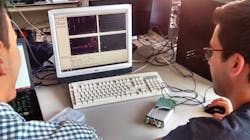
1. Here, students are measuring circuits included in the VNA Sandbox.
So, that in a nutshell outlines the problem we faced: We needed to get several spectrum analyzers and VNAs to set up a new RF laboratory, with a budget of a few thousand euros each year. Looking to the websites of traditional suppliers was quite depressing, with prices normally higher than 15.000 or 20.000 €.
I considered buying second-hand instruments, and I remember several suppliers had eBay listings for repaired instruments at affordable prices. But they were instruments from the 1980s—what happens if they break? Are spare parts available? The warranties were quite limited and, honestly, I didn’t want to make the students come back to the 3½-in. diskettes and the serial port to take out their data.
Fortunately, we live in a time where low-cost developments are becoming more common. I discovered MegiQ VNAs and it was exactly what we needed. The VNA works like a traditional analyzer, allowing you to configure the frequency range and output power, make SOLT calibrations, and take quite accurate measurements. It is perfect for teaching! Moreover, it is affordable!
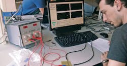
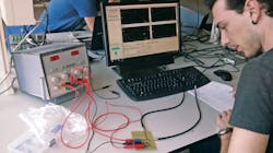
2. This student is measuring an RF switch with a VNA (right) and SMA cables.
The purpose of the RF laboratory sessions is to get the students familiar with RF instrumentation, calibrations, measurements, s2p exportation, procedures, etc. We don’t require a VNA to measure up to 20 GHz with a fancy touchscreen, the latest version of Windows, incredibly low noise, or a wide family of expensive accessories. What we need is just a professional tool to teach how this kind of instrument works. MegiQ also offers the VNA Sandbox, a learning tool that helps you get started with VNA measurements.
Today, we have three practices built around using the 4-GHz VNA-0440:
Practice 1: Measurements of impedances and S parameters
In this practice, the students familiarize themselves with the VNA, measuring different circuits included in the VNA Sandbox (Fig. 1). First, they configure the instrument, calibrate it with the UFL cables, and then characterize the low-pass, bandpass and high-pass filters and attenuator, using the markers to measure bandwidth, insertion and return losses, etc.
After that, they perform several impedance measurements, representing the results in the Smith chart. In this way, the students check the geometric places of the short circuit, the 50-Ω load, and the open circuit in the Smith chart. Finally, they measure the impedance of the LC series and LC parallel circuits, and they have to find the resonance frequency.
3. The balanced structure being measured contains directional couplers and two filters.
Practice 2: Characterization of directional couplers, dividers, and switches
This practice involves characterizing several circuits—commercial or designed at UCM—with SMA connectors. First, the students start connecting SMA-terminated cables and then calibrating. After that, they measure the directional couplers (a branch line and a rat race) and dividers, with and without 50-Ω loads, to see the importance of proper terminations. They measure the central frequency, the insertion losses, coupling, isolation, directivity, and phase differences between the outputs. Finally, the students measure a single-pole, double-throw (SPDT) switch implemented with PIN diodes, measuring the insertion losses upon selection of the different branches (Fig. 2).
Practice 3: Balanced structures
4. The balanced structure is composed of coaxial components.
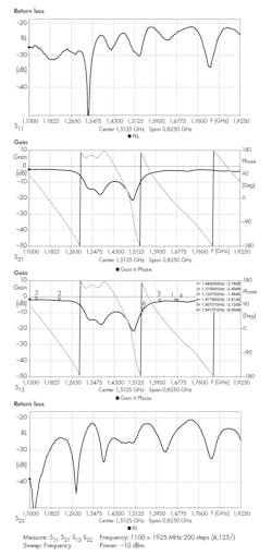
In this practice, the students characterize the different components of a balanced structure (considering the connection cables part of the filters), and then they measure the complete response of the structure (Figs. 3 and 4).
This way, they see the advantages of the structure: the good matching at all frequencies at port 1, with all the power reflected to port 3 and 4 (Fig. 5).
5. Outside the filter pass band, the reflected power can be terminated at outputs 3 and 4.
Outlook
With the success we experienced, we also decided to purchase a 6-GHz VNA-0460. The plan is to develop new practices and increase the number of testbenches. The number of enrolled students in the new degree increases every year, so our next challenge is how to deal with that growth.
Luis Ángel Tejedor has served as an Associate Professor at Complutense University of Madrid since 2016, teaching high-frequency electronics for the degree of Communications Electronics Engineering. He received a master degree in Telecommunication Engineering in 2006 and a Ph. D. in Telecommunications Engineering in 2014, both from the Polytechnic University of Madrid.
Between 2007 and 2009, he worked as RF engineer in the Eurofighter program at Indra Sistemas S.A. Since 2009, he has worked at the Physics Faculty of the Complutense University of Madrid, designing electronic systems for gamma-ray Cherenkov telescopes, in the MAGIC and CTA projects. He has over 10 years of experience designing low-frequency, high-frequency and digital circuits.
About the Author
Luis Ángel Tejedor
Associate Professor
Luis Ángel Tejedor has served as an Associate Professor at Complutense University of Madrid since 2016, teaching high-frequency electronics for the degree of Communications Electronics Engineering. He received a master degree in Telecommunication Engineering in 2006 and a Ph. D. in Telecommunications Engineering in 2014, both from the Polytechnic University of Madrid.
Between 2007 and 2009, he worked as RF engineer in the Eurofighter program at Indra Sistemas S.A. Since 2009, he has worked at the Physics Faculty of the Complutense University of Madrid, designing electronic systems for gamma-ray Cherenkov telescopes, in the MAGIC and CTA projects. He has over 10 years of experience designing low-frequency, high-frequency and digital circuits.
