Download this article in PDF format.
By Steven Xie, Analog Devices Inc.
Today’s successive-approximation-register (SAR) analog-to-digital converters (ADCs) and sigma-delta ADCs are known for their high resolution and low noise. Nevertheless, achieving signal-to-noise (SNR) performance specified in the datasheet can be difficult. An even greater challenge is optimizing ADC spurious-free dynamic range (SFDR) by establishing a reliable noise floor without incurring spurs in the system signal chain. Such spurs are often caused by improper circuitry surrounding the ADC, or can result from external interference, especially in harsh operating environments.
This article will describe techniques for identifying the root causes of spur issues in high-resolution, precision ADC applications, and offer solutions to solve them while improving end-system EMC capability and reliability. Use cases include spurs caused by dc-dc power-supply radiation, ac-ac adapter noise, analog input cable noise, and room lighting.
Spurs and SFDR
It’s common knowledge that spurious-free dynamic range (SFDR) represents the smallest power signal that can be distinguished from a large interfering signal. For current high-resolution, precision ADCs, the SFDR is typically dominated by the dynamic range between a fundamental frequency and the second or third harmonic of the fundamental frequency of interest. However, certain spurs can limit the performance due to other aspects of the system.
The spurs can be categorized as input-frequency-dependent spurs and fixed-frequency spurs. Input-frequency-dependent spurs are related to harmonic or nonlinearity performance. This article will focus on the fixed-frequency spurs caused by power supplies, external references, digital interfacing, external interference, and more. Based on the application, these types of spurs can either be reduced or avoided entirely to help achieve maximum signal-chain performance.
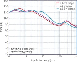
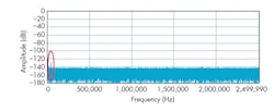
1. The plot indicates AD7616 PSRR versus ripple frequency.
Spur Issues Caused by On-Board DC-DC Power-Supply Noise
Typically, LDOs are the suggested solution for generating low-noise power-supply rails for precision ADCs in precision measurement systems because of the dc-dc switching regulator’s higher ripple noise. The fixed-frequency or pulse-width-modulated switching regulators provide switching ripple that’s usually at a fixed frequency ranging from tens of kilohertz to a couple of megahertz. The noise at the fixed frequency can feed into the ADC conversion codes via the ADC’s power-supply rejection-ratio (PSRR) mechanism.
Some designers may use dc-dc switching regulators for precision ADC applications due to limited budget or board space. They have to limit the ripple noise or use ADCs with high PSRR to make sure that the ripple noise is below the ADC noise floor in order to achieve signal-chain performance. Otherwise, there could be spurs at the switching frequency in the ADC’s output spectrum, which may degrade signal-chain dynamic range.
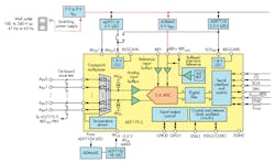
The AD7616 is a 16-bit data-acquisition system (DAS) that supports dual-simultaneous sampling of 16 channels for power line monitoring. It has a very high PSRR and is effective at rejecting/attenuating the switching ripple. For example, a dc-dc switching power supply with 100-mV p-p ripple noise at 100 kHz is used for the AD7616, which has a VCC of 5 V with ±10-V input range.
The digital code noise caused by the ripple noise is:
The level of ripple showing up in the ADC output (Fig. 1) is low for a 16-bit converter. ADCs exhibiting high PSRR performance make it possible to use switching regulators in precision measurement systems.
Spur Issues Caused by DC-DC Power-Supply Radiation
Using a high-PSRR ADC does not ensure that switching regulators will not cause problems in precision measurement systems. The ripple noise from switching regulators could feed into the ADC’s digital codes through other ways.
To illustrate, the AD4003 is a low-noise, low-power, 18-bit, 2-Msample/s SAR ADC. During EVAL-AD4003FMCZ evaluation board ac performance testing, a spur at a level of about –115 dBFS was found at around 277.5 kHz; the spur and its second harmonic appeared as shown in Figure 2.
2. Spur issue as seen on an EVAL-AD4003FMCZ evaluation board.
First, it was confirmed that the AD4003 power supplies were not causing the spurs. Then, tests were performed to determine if the spurs were coming from the analog input:
- The spurs decreased when the differential analog-input conditioning circuitry was removed.
- The spurs decreased when a narrow bandwidth RC filter (e.g., 1 kΩ, 10 nF) was inserted at the front end of the AD4003 buffer amplifier (ADA4807-1).
These results show that the noise causing the spurs may pass through the conditioning circuitry and into the AD4003’s analog inputs. Next, the sensor output was disconnected and the conditioning circuitry removed, leaving only the VREF/2 CM voltage input at the noninverting input of the ADA4807-1. However, the spurs remained and at a similar level.
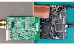
3. VADJ_FMC inductor L5 covered by copper-foil shield.
It was then suspected that the interference source was located around the EVAL-AD4003FMCZ signal chain. To prove this, a copper-foil shield was placed at various locations on the EVAL-AD4003FMCZ board and the controller SDP-H1 board. It was determined that when the copper-foil shield was placed over the dc-to-dc power supplies on the SDP-H1 board (Fig. 3), the spurs would disappear. The spur frequency of 277.5 kHz matches the programmed switching frequency of the ADP2323 regulator. Figure 4 shows the 3.3 V VADJ_FMC switching frequency power as captured by the EVAL-AD7616SDZ GUI FFT.
4. VADJ_FMC 3.3-V switching ripple captured by EVAL-AD7616SDZ GUI FFT.
The conclusion was reached that the dc-dc switching frequency interference was being emitted by the 8.2-µH inductor (L5). The interference was being injected into the signal chain at the input of buffer amplifier ADA4807-1, where it then went into the AD4003 ADC’s analog input.
Possible solutions to this spur issue caused by the dc-dc power converter are:
- Use a low-pass filter at the front end of the AD4003 ADC to attenuate the coupled dc-dc switching frequency interference to a level that meets the design target (that is, spur buried in noise floor) if the application bandwidth allows it.
- Use the new SDP-H1 board (BOM Rev 1.4), which uses a shielded inductor for L5. The radiated interference power is reduced, so the spurs captured in the AD4003 ADC’s spectrum are much lower.
- The VADJ_FMC voltage level can be programmed by the EEPROM on the EVAL-AD4003FMCZ board. It was found that using a lower voltage level, such as 2.5 V for VADJ_FMC, caused the spurs to disappear, too.
Spur Issues Caused by AC-DC Adapter Noise Coupling Through External Reference
ADCs quantize an analog signal into a digital code as referred to the ADCs’ dc reference voltage level. Therefore, the noise on the dc reference input will directly feed into the ADC’s output digital codes.
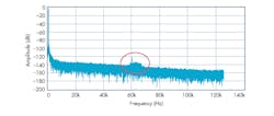
5. Cluster of spurs as seen on the EVAL-AD7175-2SDZ evaluation board.
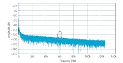
The AD7175-2 is a low-noise, fast-settling, multiplexed, 2-/4-channel (fully/pseudo differential) Σ-Δ ADC for low-bandwidth inputs. During the EVAL-AD7175SDZ evaluation board’s signal-chain test, a cluster of spurs around 60 kHz was captured (Fig. 5).
6. The spur issue was revealed using the EVAL-AD7175-2SDZ evaluation board.
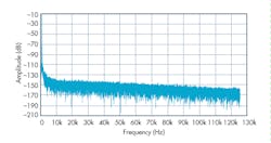
The AD7175-2 ADC’s power supplies and analog-conditioning circuitries were evaluated and found to be good. However, as shown in Figure 6, the AD7175-2’s 5-V reference input is generated by the ADR445 reference supplied by 9-V dc from an ac-dc adapter that’s external to the evaluation board. Next, a bench 9-V dc power module was substituted for the adapter. As a result, the cluster of spurs disappeared, leaving only a narrow spur at 60 kHz (Fig. 7).
7. The cluster of spurs removed on EVAL-AD7175-2SDZ eval board.
8. This 3.3-V VADJ_FMC switching ripple was captured by EVAL-AD7616SDZ GUI FFT.
The 9-V output ac-dc adapter was tested with the EVAL-AD7616SDZ GUI FFT while supplying the EVAL-AD7175-2SDZ board with 320 mA of current output (Fig. 8). The switching frequency power at the ADR445 reference’s power pin is about –70 dBFS with an AD7616 ±10-V input range, which means 6.325 mV p-p or –64 dBFS at an AD7175-2 ±5-V input range:
This power switching ripple noise feeds into the AD7175-2 ADC and shows up in the digital codes with some attenuation as stated below:
- The ADR445 reference’s datasheet specifies a PSRR of 49 dB at 60 kHz.
- The ADR445 reference’s output impedance is about 4.2 Ω at 60 kHz. It combines with the 4.8-µF reservoir caps, giving a further 18 dB of attention.
- In addition, the AD7175-2 ADC’s digital filter sinc5 + sinc1 adds about –3 dB of attenuation at 60 kHz, when the output data rate is 256 ksamples/s.
This calculated –134-dBFS level is very close to the level of the captured –130-dBFS cluster of spurs (not including the highest narrow spur) shown in Fig. 5. This verifies that the cluster of spurs is caused by the ac-dc adapter’s switching ripple feeding through the external reference ADR445. The remaining narrow spur will be resolved in the subsequent section.
Spur Issues Caused by Interference Injected into Signal Chain
In the hardware system, there’s generally a long signal chain from the input sensor to the input of the precision converters. This signal chain includes connecting cables, connectors, routing wires, scaling and conditioning circuitries, ADC drivers, and more. The potential is high for external interference to inject into the analog input signal chain and cause ADC spurs.
Spur Issues Caused by Power Cable Interference into Signal Chain
9. An oscilloscope power supply cable caused a spur.
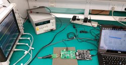
During the investigation of the remaining narrow spur on the EVAL-AD7175-2SDZ evaluation board’s spectral output, a digital oscilloscope was observed operating on the test bench. As shown in Figure 9, the scope’s 220-V ac power supply cable (the black one) was overlapping the EVAL-AD7175-2SDZ EVB’s analog input cable (the gray one). When the oscilloscope was turned off or its power cable was physically moved away from the analog input cable, the narrow spur at 60 kHz disappeared, as shown in Figure 10.
10. All spurs were removed on the EVAL-AD7175-2SDZ evaluation board.
In the system cabinet, care should be taken in routing the cables from the sensor to the DAQ board. It’s a good practice to keep the low-level sensitive analog signals separated from the high-current power lines.
Spur Issues Caused by Lamp Radiation
A spur appeared on the FFT spectrum while testing the EVAL-AD7960FMCZ evaluation board. As shown in Figure 11, the spur level was about –130 dB at 40 kHz.
11. Spurs experienced on the EVAL-AD7960FMCZ were caused by fluorescent lighting radiation.
The 40 kHz seemed to be unrelated to any of the signal frequencies that appear on the EVAL-AD7960FMCZ board and its controller board, SDP-H1. The next approach to finding the source of the spur was to clear the testbench in case there was something generating external interference. When the fluorescent light on the bench rack was turned off, the spur disappeared.
Furthermore, it was found that as the EVAL-AD7960FMCZ board was put closer to the light, the 40-kHz spur would get higher (Fig. 12). An additional RC filter (such as 1 kΩ, 10 nF) was placed at the front of the buffer amplifier ADA4899-1 and the spur decreased about 10 dB. That meant that the fluorescent light was radiating disturbance into the signal-chain path at the front of the noninverting input of the buffer amplifier.
12. Fluorescent lighting in proximity to the EVAL-AD7960FMCZ board.
For systems that operate in a lighted environment, installing a shielding case over the front-end circuitry can help protect it from radiating interference and optimize signal-chain performance.
Spur Issues Caused by a Long Analog Input Cable
During the evaluation of the EVAL-AD4003FMCZ board, an AP SY2712 signal generator was used to drive a low-noise and low-THD sine wave to the analog inputs through an XLR microphone cable (about 2 meters long). In this setup, a spur was apparent at a level of about –125 dB at 700 kHz (Fig. 13).
13. Spur on EVAL-AD4003FMCZ eval board caused by XLR cable.
Investigation of the spur revealed three ways to solve the problem:
- Bypass the 2-m-long XLR microphone cable and short the AP-balanced output XLR male connector to the interposer XLR female connector (Fig. 14).
- Set the signal source SY2712’s output impedance from Z-Out = 40 Ω to Z-Out = 600 Ω.
- The spur becomes smaller when a narrow bandwidth RC filter (such as 1 kΩ, 10 nF) is inserted in the signal chain at the front end of the AD4003’s buffer amplifier, the ADA4807-1.
14. AP driving the EVAL-AD4003FMCZ board through a long XLR cable.
Finally, the conclusion was reached that the mismatch in the signal source’s output impedance, and the long XLR cable, caused the high-frequency spur at 700 kHz.
References
Beavers, Ian. “Understanding Spurious-Free Dynamic Range in Wideband GSPS ADCs.” Analog Devices Inc., 2014.
McCarthy, Aine. AD7175-2 Evaluation Kits. Analog Devices Inc.
Pachchigar, Maithil. AD4003 Evaluation Kits. Analog Devices Inc.
Walsh, Alan. “Powering a Precision SAR ADC Using A High Efficiency, Ultralow Power Switcher in Power Sensitive Applications.” Analog Devices Inc., 2016.
