Static common-mode specifications have been the traditional standard used to measure isolators and compare devices with different construction or technologies. However, that standard is no longer an adequate measurement and comparison parameter. Instead, it is increasingly critical to understand common-mode rejection (CMR) performance when the end system is active, not static, with the isolator’s input and output signals changing. To make the selection process more rigorous, designers should look at devices based on different isolation techniques—optical, magnetic, capacitive, and RF—with this perspective.
The oldest and most refined isolation technology is based on light in the infrared range, and optical technology is the only technology covered by the internationally recognized IEC 60747-5-5 safety standard. Also known as a photocoupler or an optoisolator, an optocoupler is an optically coupled semiconductor device that allows signals to be transferred between circuits or systems, while keeping those circuits or systems electrically or galvanically isolated from each other. Single- and multiple-channel optocouplers are available.
Inside a representative optocoupler, sufficient insulation thickness is used to minimize parasitic capacitive coupling between the input and output sides, which, in turn, increases optocoupler CMR (Fig. 1). In addition, Avago enhances optocoupler CMR further by using an internal Faraday shield that surrounds the photodetector. The shield allows optical transmission but diverts any electrical interference to ground.
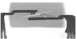
In its simplest form, an optocoupler consists of an LED for signal transmission and a photo-sensor for signal detection, with an insulating voltage dielectric material between the emitter and the detector. The x-ray of a packaged device shows the location of basic components from a side perspective (Fig. 2). The dielectric insulation material between the emitter and detector is absolutely essential to establish a high-voltage withstand capability, as defined by international safety standards, as its thickness and dielectric strength determine the high-voltage insulation capability of the optocoupler.
Packages can also make isolators more reliable and meet more stringent safety standards. Avago optocouplers achieve better CMR performance, because the distance through insulation (DTI) distance, as measured from the input LED to the photodetector of the optocoupler, is greater than the DTI of non-optical isolators. Creepage and clearance package specifications are also defined in safety standards and appear on product data sheets. Product specifications are often a function of a specific package type.
How Is Static CMR Measured?
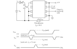
In the CMR test circuit with associated waveforms of Figure 3, a pulse simulating the common-mode noise is injected between the input and output side of the isolator. The resulting disruption, if any, is observed at the output. The test is passed if the output remains as it should and does not switch its logic level, even if only momentarily. (The two-way switch at the input allows a CMR measurement to be made when the output is both at logic high or low state.)
CMR performance can depend on the output state of the isolator. CMRL quantifies CMR measured when the output is at a logic LOW, and CMRH specifies common mode rejection with a logic HIGH output. CMRL and CMRH measured with static dc input and output conditions indicate how an end application might respond when in an idle or standby state. However, it is often also critical to understand CMR performance when the system is active with the isolator’s input and output signals changing.
What Is Dynamic CMR?
The dynamic CMR specification is determined by measuring CMR with the inputs and outputs switching, thereby simulating the actual operation of an isolator. The dynamic CMR test setup is similar to the static CMR test setup except that an oscillator actively switches the input signal (Fig. 4). A signal generator should never be used in place of the oscillator, because injection of a high common-mode voltage could lead to a destructive voltage spike on the signal generator’s ground line.
Dynamic CMR Comparison
It is easy to compare isolation products of different technology or manufacturers. Dynamic CMR performance of isolators based on optical, magnetic, capacitive, and RF technology were tested at a VDD of 5 V and with a 5-MHz oscillator to simulate an input data rate of 10 MBd.
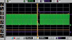
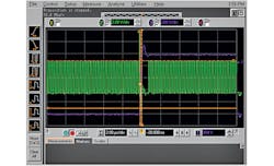
Among the isolators tested, Avago’s ultra-low-power 10-MBd digital optocoupler, the ACPL-M61L, showed the best dynamic CMR performance. The output did not show any significant sign of disturbance even after applying a high-voltage 48-kV/μs pulse with a common-mode voltage of 1 kV. This exceeded the 35-kV/μs typical datasheet value, with a 1-kV common-mode voltage. The oscilloscope image taken during the dynamic CMR test of the Avago ACPL-M61L shows this performance (Fig. 5).
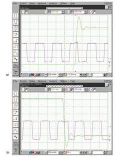
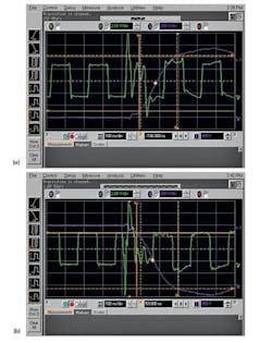
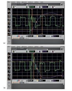
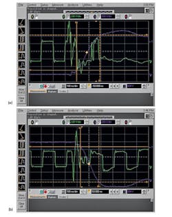
The measured dynamic CMR performance of non-optical isolators was significantly lower compared to optocouplers. None of the alternative technology isolators tested—magnetic, capacitive, or RF—achieved a dynamic CMR value greater than 5 kV/μs with a common-mode voltage of 1 kV. Waveforms for a magnetic isolator (Fig. 6), capacitive isolator (Fig. 7), and RF isolator (Fig. 8), were affected by the high-voltage pulse, resulting in an erroneous output. The most affected of all types tested was the RF isolator, which became temporarily inoperative and caused the output to miss input pulses (Fig. 9).
High-voltage common-mode noise is inevitable in industrial environments, but a proper choice of isolator technology helps protect signal integrity for critical data transmission in such harsh environments. Application environments that require a safe and rugged isolation solution for world markets include industrial valve control, motor control, wind and solar power, transportation (automotive, train and locomotive), medical (MRI and CAT), elevator and passenger transport systems, white goods, instrumentation, and smart meters.
Avago’s advanced IC design and proprietary package technology improves optocoupler high-voltage performance and noise rejection while also making low-power solutions possible. Longer-life LEDs, with less degradation of their current-transfer ratio over time, make optocouplers a reliable, long-term isolation solution where safety and performance are needed.
References
- Applications and products for isolation
- ACPL-M61L-000E Ultra Low Power 10-MBd Digital CMOS Optocoupler datasheet
- Ultra-Low Power 10-MBd Digital CMOS Optocoupler: ACPL-M61L/064L SPI Evaluation Board
- Ensure Safe System Operation with Certified Isolator Devices
- Fieldbus Applications with Optocouplers
- Galvanic Isolation: Choosing the right isolation device (Video)
- Isolation Design: Reinforced Safety and Isolation (Video)
