A while back, I did an article about Bob Pease’s “hassler” circuit. Bob adapted it from a Bob Widlar circuit that would sense someone talking loudly in his office and then emit a shrill hissing noise. After getting familiar with that circuit, I thought about a similar one that would make a shushing noise when people would talk loudly. I expect it will be wildly popular with librarians, as well as anti-social engineers.
As much as I like analog, a circuit that detects a threshold and then creates an event seemed to suggest at least a semi-digital solution. I thought about using one of those recording chips like in greeting cards. You could just record someone, perhaps a friendly librarian, saying “shush,” and then use a threshold circuit to trigger the playback. I thought this was a bit too boring of a design. It’s almost like you have to do programming. So rather than a sampled-data playback, I thought it would be more fun to fabricate the shushing noise, like an old analog musical synthesizer.
Block Diagram
The block diagram of the circuit has the same input and output as Bob Pease’s circuit (Fig. 1). A Radio Shack microphone senses ambient noise, while a complementary transistor unity-gain buffer outputs the audio to a Radio Shack speaker. The fact that Radio Shack went bankrupt may create some sourcing issues in high-volume production, so be careful.
1. The shush circuit block diagram uses many analog principles to output a shushing noise when the microphone picks up any loud voices.
The Schematic
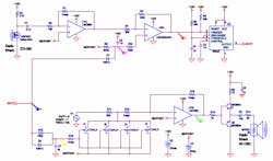
As Professor McLaughlin taught us back at GMI, sometimes it’s easier to understand a schematic looking from the output back to the input (Fig. 2). You know you have to drive a low-impedance speaker. So, like Pease, use a pair of complementary (PNP and NPN) bipolar transistors to drive the speaker. Since the stage is single-ended, driven by a single positive 12-V supply, it uses a large capacitor to ac-couple the output to the speaker.
2. The circuit for simulation substitutes a 10-kHz sine wave for the white-noise generator. Voltage marker flags correspond to the simulation output trace colors in the figures below.
The output stage is driven by amplifier U1B. It’s set up as an inverting amplifier, also biased at 6-V—the midpoint of the power-supply rail. The 1-MΩ resistors might cause offset and noise problems in a different application, but the whole purpose of this amp is to amplify noise, so a little more won’t hurt. Because the LMC662 has negligible input bias current, it would not create an output offset due to the large resistor values.
The input to U1B is a voltage-variable attenuator fed from a white or pink noise source. Rather than try to model this tricky circuit in Spice, I just used a 10-kHz oscillator to represent the noise. In a physical circuit, you could bias up a Zener diode and amplify the result to make pink noise.
The variable attenuator is made by four paralleled JFET transistors. A positive voltage on the gates turns the JFETs off and allows the noise signal to pass to the input of U1B. The diode D2 raises the gate voltage as soon as the gate signal from the one-shot 555 goes high. That creates the sharp consonant attack of the “shush” sound. Once the gate signal goes away, the diode reverse-biases, and capacitor C7 slowly discharges, sweeping the gate voltage slowly negative. This makes the soft lingering “shhhh” decay of the shush sound.
Since you need a narrow digital pulse to trigger the “shush” sound, a 555 timer IC set up as a one-shot does the deed. Use a CMOS version to reduce the power needed from the 12-V supply. Be sure that your Spice package accurately simulates a one-shot timer. I spent over an hour just doing a simulation on the 555 chip to make sure it acted like a real chip.
The gate output of the 555 one-shot circuit goes to the attenuator, but it also feeds back to the sensing amplifier U2A that drives the trigger input of the one-shot. A 555 triggers on a falling edge, which provides a blanking function. When the one-shot triggers, it drives its own input amp all the way to the positive rail. This ensures that there will be no more trigger events until the gate signal times out and capacitor C2 charges up to let the bias of U2A float back to the midpoint voltage. Since the blanking circuit drives the amplifier to the positive rail, I used a rail-to-rail part, the LMC8284.
This gets us to the start of the circuit. The microphone feeds a single-ended amplifier working on 12 V, like Pease’s circuit. To properly bias the amplifier, you need a “midpoint” voltage of 6 V, so that the amplifier output can swing down to 0 and up to 12 V.
Don’t Trust Spice
Now all of this Spice stuff is just dandy, but it leaves you a long way from a working circuit. Not modeled by the simulation is the interaction between the output sound and microphone. I tried to blank it out, but it still might interact. You might have to put a high-pass filter on the output, and a low-pass filter on the input, so that the circuit does not get into a feedback loop.
In addition, you have to make a real pink noise source. You can do this by amplifying the noise from a Zener diode or a reverse-biased base-emitter junction that you intentionally put into breakdown, much like a Zener. Another method is to put a resistor between the plus and minus inputs of an op amp, thereby increasing the noise gain, which you can then amplify even more. Another circuit gains up resistor noise and runs it through a flicker filter so that the noise is flat over frequency
Another shortcoming of Spice is that it does not care about the unused amplifiers in the quad LMC8284 package. Even though it’s a rail-to-rail amp, just lacing the outputs to power or ground might still make the amp draw more quiescent current. Best practice is to set the unused amps as a voltage follower, and then bias up the plus input to somewhere in between the rails, at least a volt or two away from either rail.
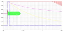
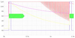
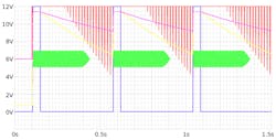
Be aware of all these caveats when looking at the Spice simulation output. Once nice aspect of the circuit is that the “shushes” come faster with increasing input sound. With the microphone simulated as a delayed sinusoid of 13 mV, the shush outputs happen over 1.5 seconds apart (Fig 3). When the microphone output raises to 50 mV, the shush sounds come 1.4 seconds apart (Fig 4). With loud noises, the 120-mV output of the microphone results in a shush sound happening every half-second or so (Fig. 5).
3. The simulation output with a 13-mV sine wave from the microphone results in a “shush” every couple of seconds.
4. With a louder input, 50 mV, the shush sounds happen every 1.3 seconds.
5. With very loud noises represented by a 120-mV microphone output, the “shushes” happen every half-second.
Who Needs Digital?
Sure, you could feed the input into a microcontroller and emulate the same behavior, but it would take an awful lot of clerical work doing the programming. Another problem with sampled data systems is that they consume more power. If the micro has to constantly run while it samples the microphone, don’t expect a lot of battery life.
Meanwhile, this analog circuit only uses minuscule power as it monitors the microphone, and the power only increases as it’s making the “shush” sound. It would be fun to try and make the circuit ultra-low power. I wonder if using a large resistor on the microphone would make it noisier, and then you could filter off that noise to make the “shush” sound.
Learning how to program a micro can be fun and challenging, but I find it much more rewarding to learn the principles of analog electronics, instead of typing skills. Meanwhile, let’s hope some offshore supplier sees this article and makes a little $3 gizmo that does the same thing. I will be their first customer.


