This article is part of the Ideas for Design Series: Vol. 3, No. 2
In many industrial and commercial situations, there is often a need to energize or de-energize equipment that is remotely located or select one of two modes of operation for the equipment. This can be done via a hard-wired, RF, or even audio link, each with advantages and disadvantages in cost, reliability, maintenance, ease of installation, and longevity. For this application, a physical link was possible but difficult, so a wireless system was chosen.
Related Articles
- Remote Control Receiver Accepts Industrial Chores
- Combine Solar Panels And ZigBee For Remote Power Management
- Get Ready For Next-Generation RF4CE Remotes And STBs
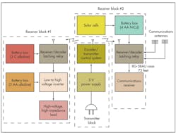
This two-channel, RF-based control system initiates one of four system activations based on a low-cost, three-module control system that allows the user to control the action of two remote circuits/loads (Fig. 1).
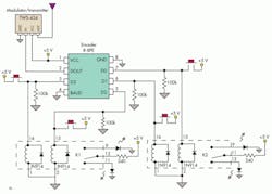
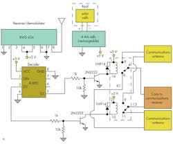
The relays in the transmitter and receivers use the standard low-side switching configuration with a 2N2222 transistor to pull down the ground side of the coil and energize the coil, as well as a 1N914 diode across the coil for protection against inductive spikes when the relay is de-energized. Modules from Reynolds Electronics (www.rentron.com) were used to simplify the design.
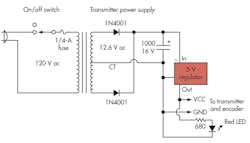
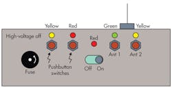
In the installation, the transmitter is located at the ground floor level and is powered via the 120-V ac line (Fig. 3).
Pushing one of four momentary pushbutton switches activates the transmitter. The transmitter was based on a small, low-cost printed-circuit module (TWS-434) that generates an output at 433.92 MHz and is modulated via a separate R-8PE encoder module. The tested maximum range of the transmitter module with a corresponding receiver module was approximately 200 yards (180 m).
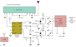
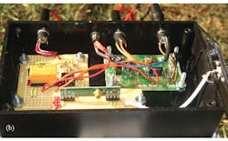
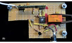
The equipment associated with receiver block #1 is located at ground-floor level 32 feet (9 m) from the transmitter (Fig. 4).
The role of this module, which consists of an RWS-434 demodulator, an R-8PD decoder, and a latching relay (Panasonic model SDE-SL2-DC5V, a low-power with 36-mA pull-in current) is to enable a user to “chase” invasive wildlife via activation of an operator-controlled “tickler circuit” (a high-voltage, high-impedance module; details not shown) .
The two left-most pushbutton switches on the transmitter front panel provide a momentary input to data channels D0 and D1, the “energize” and “de-energize” commands that activate and de-activate the tickler circuit via this receiver (Fig. 5). Latching relays are used so the user does not have to hold the pushbuttons down.
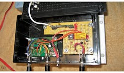
Receiver block #2 is used for an unrelated application from the same transmitter (Fig. 6). It enables the user to select the antenna output of one of two co-located antennas on the roof and connect the desired output to a communications receiver via a coax cable.
Though a separate cable for each antenna could have been used, snaking the additional cable needed through two floor levels and two walls was undesirable due to the completion of building remodeling. The solution was to use a data-selection receiver that enables a latching relay to route the signal from one or the other antenna to a common coax.
A 120-V ac source to power the receiver circuit and latching relay was not practical, so two solar panels from a surplus electronics dealer feed a battery pack of four AA-size nickel-cadmium (NiCd) cells. To select the output of a particular antenna, the user momentarily depresses one of the two buttons located on the right side of the transmitter panel. This activates either the D2 or D3 inputs to the transmitter encoder and thus generates the corresponding decoder output.
Each of the three antennas was constructed using a UG-88 connector (a male BNC plug) where the center pin was replaced by a 7-in. (18 cm) piece of 0.050-in. (1.3 mm) diameter brazing rod. The brazing rod was epoxied into the connector and a 0.75-in. (20 mm) wooden bead was added to the end of each rod for safety.
This file type includes high resolution graphics and schematics when applicable.
Acknowledgements
The author would like to thank Oscar Ramsey, who did the assembly and assisted in the system testing; David Morrison, Carl Olsen, and Milford Craig for editorial contributions; and Colin White for producing the iniital schematic drawings.
Read more articles from the Ideas for Design Series: Vol. 3, No. 2
William Rynone, PhD, PE, Rynone Engineering, has designed electronics and is presently a technical writer. He taught electrical engineering at the U.S. Naval Academy and Johns Hopkins University. He is also president of the Annapolis Chapter of the Maryland Society of Professional Engineers. He can be reached at [email protected].

