Engineers occasionally need to measure very low frequencies between 1 and 100 Hz, but getting an accurate reading is difficult. The solutions are to use a suitably long gate time, or get an expensive counter that can compute frequency from period. The inexpensive circuit here effectively upconverts the input frequency to a higher range so it can be read easily and more accurately, and can be implemented as a block within a larger circuit.
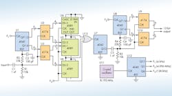
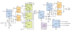
At the core of the design are 4089 rate-multiplier ICs (U4 to U6), which output a frequency at N × f(in)/ 16, where N is the 4-bit code applied to the input frequency f(in). By cascading three of these ICs, the equation becomes N x f(in)/4096. Two 7497 6-bit ICs may be used instead of the three 4089 devices to reduce package count.
U1 is a 12-bit counter that measures the period of the input; the count is latched in U2 and U3. This causes the rate multipliers to output a frequency that’s directly proportional to the input period. U7 divides this by 4096 to remove jitter and make the period more easily measurable. As with U1, U8 measures this period, which is latched in U9 and U10.
This file type includes high resolution graphics and schematics when applicable.
This provides a measure of the period of U7's output, which is inversely proportional to its frequency. Because that frequency was proportional to the input's period, the value latched by U9 and U10 is directly proportional to the input frequency, but at much higher resolution, and can be measured much more quickly. U11 and U12 generate all of the needed timing signals. Different frequencies can be chosen, depending on the range to be measured.
An example helps illustrate the process. For f(in) = 4 Hz and f1 = 4000 Hz, U1 will count to 1000 before being latched by U2 and U3. This will cause rate multipliers U4 to U6 to generate 1000 × f2/4096, or 1 MHz for f2 = 4.096 MHz. U7 divides this down to 244 Hz, and U8 measures the period as f3/244 Hz, or 524 for f3 = 128 kHz.
Therefore, we have multiplied the input frequency by a factor of 131 (524 Hz/4 Hz), so the circuit can resolve to 0.0076 Hz in one second. This would otherwise take two minutes using the original 4-Hz input.
Karen Hunsberger, an independent consultant, holds a B.Sc (Hon) from the University of Waterloo and a B.Ed. from the University of Western Ontario. She enjoys working on alternative energy and farm/garden designs.


