Download this article in PDF format.
What you’ll learn:
- How to replace MOSFETs with load switches, and the impact of on-resistance.
- Swapping out diodes with ideal diodes, and the use of ideal-diode controllers.
- Why replacing fuses and resettable fuses with eFuses is a smart play.
Demand for greater power density and smaller printed circuit boards (PCBs) continues to escalate within markets such as building automation and automotive infotainment. To keep up with these trends, there’s a push to convert discrete power circuits to fully or partially integrated solutions.
Discrete components such as diodes, fuses, and metal-oxide semiconductor field-effect transistors (MOSFETs) are being replaced by integrated devices that not only replicate their functionality, but also provide improved performance—including up to 5X higher power density—and other features benefiting the overall application. This article highlights some of the common discrete circuits used for power distribution and protection, as well as the most appropriate integrated solutions to replace them.
Replacing MOSFETs with Load Switches
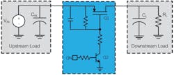
In analog power distribution, discrete MOSFETs are used to connect and disconnect a power supply to a load. The most common type of MOSFET used for these applications is a P-type metal-oxide semiconductor (PMOS) due to its ease of use and low cost. By implementing three resistors, a capacitor, and a control FET, it’s possible to create a simple active-high switching solution with a controlled turn-on for limiting capacitive-load inrush current (Fig. 1).
While this circuit can electrically switch a downstream load on and off, it has shortcomings that make it difficult to use in modern designs. The biggest concern is the ability to increase system power density to achieve higher power without impacting solution size. With six discrete components and an average solution size of 17 mm2, it’s very likely this circuit can be improved through integration. The solution also has no protection or additional features to benefit the rest of the system, such as thermal shutdown or power good indication.
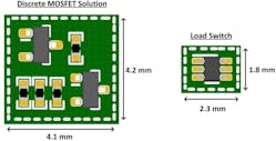
A load switch integrates the functionality of the MOSFET switching solution with added features such as current limiting and output discharge. With an enable pin, the load switch is able to connect and disconnect the input to the output with a linearly controlled voltage ramp to manage inrush current. By using a load switch instead of a discrete MOSFET circuit, the solution size can be reduced to 4 mm2 or smaller. This results in a 3.5X improvement in power density. Figure 2 compares the solution size of a discrete implementation to the TPS22919, an integrated load switch from Texas Instruments (TI).
On-resistance is the specification that determines how efficiently power is transferred from supply to load. Thus, it’s used to compare performance between two switching solutions. Equations 1 and 2 show how a higher on-resistance directly results in a larger voltage drop across the switch and increase in power loss:
Power loss = ILOAD2 × RON (1)
Voltage drop = ILOAD × RON (2)
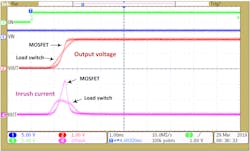
The on-resistance of a MOSFET is proportional to the gate-source voltage (VGS). In the discrete solution, this VGS voltage is usually controlled using a resistor and capacitor (RC) circuit. The RC control approach results in a nonlinear ramp at the output. The nonlinear ramp causes higher peak inrush current, thereby burdening the input source and causing the potential for supply drooping.
A load switch linearly controls the VGS voltage, resulting in a linear voltage ramp at the output and thus lowering the peak inrush current (Fig. 3).
In addition to inrush current control, the load switches integrate other features such as thermal shutdown, quick output discharge, short-circuit protection, adjustable current limit, and rise time. These features eliminate the need for a safe-operating-area (SOA) curve since the load switch will protect itself during high-stress events. Features like adjustable slew rate and adjustable output discharge allow for greater control over the turn-on and turn-off profile of the load switch, enabling better inrush current management and more controlled power-off. For power-sequencing applications, load switch features like power good can enable downstream devices or turn on the next rail in a sequence.
Replacing Diodes with Ideal Diodes
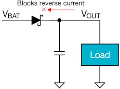
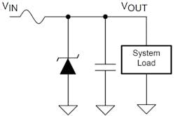
Typically, diodes are used for reverse-current blocking and reverse-polarity protection. Diodes are placed in series with power rails to protect the power supply during a fault event (Fig. 4).
However, placing a diode in series to a power-supply output causes a voltage drop across the diode (300 mV for a typical Schottky diode and 700 mV for a traditional diode). Therefore, the power loss in the Schottky diode can be as high as 300 mW for a 1-A load current—see Equation 3. To minimize the power loss, a higher-power diode is often used for high-power systems.
Power dissipation = ILOAD × VFWD (3)
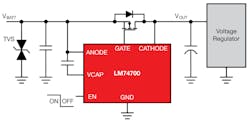
Alternatively, an ideal-diode controller can be used to drive an external MOSFET that acts like an ideal diode. The MOSFET is placed in series with the power rail so that its body diode faces from supply to load. For example, the LM74700, an ideal-diode controller from TI, regulates the forward voltage from supply to load to 20 mV (Fig. 5).
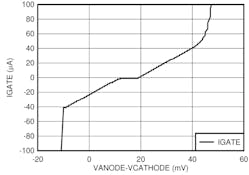
The GATE pin is tied to the gate of the MOSFET and sources or sinks current to regulate the MOSFET resistance and maintain the constant forward voltage (Fig. 6).
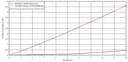
This gate voltage regulation provides a low voltage drop in the forward direction and blocks reverse current within 0.75 µs when the output voltage rises above the input voltage. The 20-mV voltage drop also results in a significant reduction in power dissipation, as shown in the comparison between the LM74700 with an external MOSFET and a Schottky diode (Fig. 7).
In addition to the reduced power dissipation, the solution size using an ideal-diode controller and a discrete MOSFET is 5X smaller than a high-power DDPAK Schottky diode.
Replacing Fuses and PTCs with eFuses
Fuses are protection devices that protect the power supply from overload or a short-circuit event. They’re placed in series between the power supply and load. During a fault event (overload or short circuit), the fuse breaks open, disconnecting the supply from the load. Traditional fuses break permanently during the fault condition. Consequently, a replacement fuse is required for the circuit to be operable (Fig. 8).
A discrete fuse requires an overcurrent level that’s 6X higher than the rated current for the fuse to break open. The overload current for these fuses isn’t very accurate; therefore, fuse selection for an application requires considerable analysis to avoid fuse break under nominal inrush-current conditions.
A resettable fuse is a positive-temperature-coefficient (PTC) device that increases its on-resistance with temperature. During an overload event, the excessive load current increases power loss, thereby increasing its on-resistance. The higher on-resistance helps limit the overload current and protects the circuit.
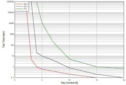
Unlike a traditional fuse, PTCs allow current to flow after the fault is cleared without replacing the device. PTCs are activated by the heating effect of an overcurrent load. As a result, the reaction time of the PTC is limited to several milliseconds due to the dependency on the ambient temperature (Fig. 9).
In addition, the on-resistance of a PTC increases after every reset. Thus, PTCs exhibit non-repeatable behavior over an extended period of use.
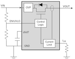
An eFuse is an active current protection device with an integrated MOSFET used to limit currents to safe levels during fault conditions. The common elements of an eFuse are a power switch to modulate the load current, a current sensing element, and control logic (Fig. 10).
The current-limit threshold can be set to a desired value through an external resistor, providing system flexibility in adjusting the current limit to a wide range. In a steady-state condition, the integrated power switch is fully turned on (similar to a discrete MOSFET switch) to minimize voltage drop in the power path.
During an overcurrent condition, the gate control transitions the integrated power switch into linear mode. The on-resistance of a MOSFET increases in the linear mode; therefore, the corresponding voltage drop across the eFuse increases to provide a constant output current.
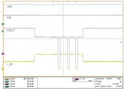
Figure 11 shows the overload response of TI’s TPS2595 eFuse with a current-limit setting of 4 A.
eFuses respond quickly to overload events (typically hundreds of microseconds) by regulating the output current to safe levels. Once the fault is removed, they recover back to normal operation without needing to be replaced. An eFuse uses a current mirror circuit to measure the load current without requiring an external sense resistor. This approach not only saves board space, but also eliminates the power loss in sense resistors. In addition, the eFuses provide better current-limiting accuracy (±5% to ±8%) over traditional fuses and PTCs.
Furthermore, eFuses integrate overvoltage protection to prevent high voltages seen on the input of the device to pass through to the load. Combined with other features such as reverse-current blocking and current monitoring, eFuses are able to handle a multitude of protection needs in a package even smaller than a fuse or PTC.
Conclusion
MOSFETs, diodes, and fuses have been used in circuits for decades, but integration has made these components obsolete in modern circuits focused on small form factor and high power density. While discrete circuits use several passive components for their functionality, integrated solutions can reduce the total number of components needed to simplify supply-chain management. Engineers looking to progress in their industry will need to utilize integrated solutions in their designs to remain competitive and maximize system performance.
A MOSFET switching solution can be simplified with a load switch to get the benefit of a linear turn-on and additional features. It’s possible to significantly reduce system power loss by lowering the voltage drop of a diode to that of an ideal diode. And an eFuse can be used in place of a PTC or fuse for more accurate overload protection and a faster response time. All of these integrated solutions provide the same functionality as their discrete counterparts with improved performance, additional features, and smaller solution sizes.

