Members can download this article in PDF format.
What you'll learn:
- How does a dc motor operate, and what's the impact of back EMF?
- Difference between continuous and stall current.
- How is current regulation applied in dc motor drivers?
Oftentimes, the motor driver and power supply are burdened by large currents upon starting a dc motor. Using examples from Monolithic Power Systems (MPS), this article looks into the current-regulation function integrated into myriad motor-driver ICs to address high-current conditions. In many cases, using current regulation can allow designers to use a smaller motor-driver IC.
For simplification, a brushed dc motor is used in all examples, but the processes described here also can be applied to brushless dc (BLDC) motor systems.
DC Motor Basics
Before discussing current limiting and regulation, it’s important to consider how a dc motor operates.
At its simplest, a dc motor can be modeled as a voltage—called the back electromotive force (EMF)—in series with a resistor. Figure 1 shows this setup. The back EMF is a voltage generated by the motor, and it’s proportional to the motor speed. The series resistance is simply the dc resistance of the winding.
Torque, the rotational force generated by the motor, is created when current flows through the motor.
If there’s no mechanical load applied to the motor and a voltage (VSRC) is applied to the motor, then the motor spins and accelerates until the back EMF (VBEMF) rises to the same level as VSRC. At this point, there’s no current flow.
When a torque is applied to the shaft, the motor slows down, causing VBEMF to decrease while creating a voltage difference between VSRC and VBEMF. This voltage difference generates a current ((VSRC − VBEMF)/RS) that flows from the source.
Note that this is a simplified, ideal approximation. In reality, there are losses, and some current is always flowing from the source.
Starting the Motor
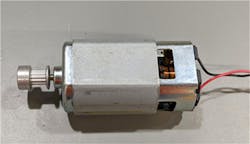
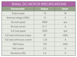
When the motor is stopped, VBEMF is 0 V. Figure 1 shows that when you first apply voltage to the motor, the current is limited only by the motor’s series resistance. This resistance is typically quite small, which results in a large current flow until the motor starts spinning. The current is usually much larger than the motor’s rated continuous current. Figure 2 shows a small DC motor, and the table below shows the motor’s specifications.
The table lists the nominal rated continuous current at 1.25 A, which corresponds to the maximum allowable continuous torque load. With this value, one might think that the motor driver only needs to support a maximum current of 1.25 A.
However, the stall current (the current through the motor at the nominal voltage when the motor is stopped) is 3.3 A. That means the motor driver must either be able to drive the stall current to get the motor spinning, or provide current limitation to soft-start the motor. Otherwise, the motor driver may activate an overcurrent protection (OCP) function. Devices that don’t provide OCP could be damaged.
In addition, the large current required to start the motor must have a power supply that can support this high current. In battery-powered systems, battery life is reduced by drawing high-current pulses, even if they are for a limited duration, so it is beneficial to limit the current when the motor starts up..
Motor-Driver Current Regulation
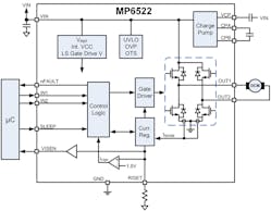
Many motor-driver ICs include some form of current limiting or current regulation. Figure 3 shows an example of a motor-driver IC—MPS’s MP6522, an H-bridge motor driver. The motor current is measured inside the IC by sensing the current in the two low-side MOSFETs (LS-FETs). This measurement is used by a current-regulation circuit.
The measured current is scaled to a voltage by a small external resistor on the RISET pin. This voltage is proportional to the motor current. If the current reaches 1.5 V, the MP6522 turns off the motor current for a fixed period of time before being re-enabled.
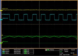
A motor has a large amount of inductance. When using current regulation to drive a motor, the current rises when the H-bridge is on, then falls when the current trip point is reached, and subsequently the driver turns the current off. The results in a triangular current waveform (green trace in Fig. 4). This waveform shows that the current is regulated by the MP6522 at a peak of about 1.5 A.
Motor Startup (Stall) Current
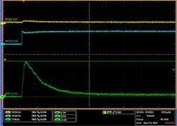
The MP6522 can be used to drive the small dc motor described above. If there’s no current regulation (RISET resistor = 0 Ω) and a 12-V power supply, then a peak current of about 3.6 A is required to start the motor. Figure 5 shows the related waveform.
The motor reaches full speed when the current levels off. In this scenario, it takes the motor about 50 ms to reach full speed.
Note that motor commutation causes the current ripple in the waveform when the motor is spinning. As the motor spins, the commutator moves from one segment to the next and transfers the current to the next winding. During these transitions, the current constantly rises and falls by a small amount. This isn’t related to the motor driver.
Using Current Regulation to Limit the Stall Current
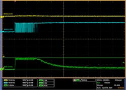
By setting the RISET resistor to 10 kΩ, the MP6522 can be set up to provide a current limit of 1.5 A. Figure 6 shows that the output turns on and off to limit the current through the dc motor.
Compared to how the motor reaches full speed in 50 ms without a current limit, it takes the motor 80 ms to reach full speed in this scenario.
Since the current is proportional to the torque applied to the motor, limiting the motor current at startup also limits the torque. Because the torque accelerates the motor from a stop to its final speed, limiting torque also limits this acceleration, meaning the motor takes longer to reach its full speed. The mechanical system’s inertia requires torque to accelerate. Therefore, if a large mass is coupled to the motor (e.g., a flywheel), then the time is extended even further.
Mechanical systems have friction, which is a static force, as well as stiction. Stiction functions similarly to friction, but it drops once the system is moving. In order to move, motors must have enough torque to overcome friction and stiction. This means that designers can’t set the motor’s startup current too low. If the current is limited too much, then the motor may not start moving at all, or it may take too much time to reach the desired speed.
Conclusion
This article explores how to use the current-regulation feature available with motor drivers, such as MPS’s MP6522, to regulate and control the large currents that flow when starting a dc motor. By understanding how to properly limit a motor’s startup current, designers not only can use smaller motor drivers, but also optimize their system’s current delivery.
