Members can download this article in PDF format.
Power modules offer many benefits. Versions with integrated inductors can simplify designs, reduce overall size, and help assure compliance with EMI standards. They let you leverage the module manufacturer’s expertise in system architecture, component selection, qualification, and sourcing, and they help cut design time and reduce PCB real-estate requirements. Moreover, when using a module, you needn’t spend time determining whether inductors and other passive components you choose will be able to withstand extended temperature ranges or repeated application of high voltages at high frequencies.
However, effective selection and application of power modules does require a basic understanding of several key concepts, including EMI compliance, high-temperature storage (HTS) test, and inductor withstand voltage. HTS test is a method of ensuring power modules’ reliability, particularly those containing inductors with powdered-iron cores. Such inductors can experience thermal aging, with degradation most likely to occur at high voltages and switching frequencies.
Sponsored Resources:
- Exploring the Value of Power Modules
- Simplify EMI design with power modules
- How Power Modules Can Save You Solution Cost
Texas Instruments’ standard HTS test takes six weeks, with the device under test (DUT) baked at 150°C. Once per week, the DUTs are removed from the temperature chamber, the inductance is measured, and then they’re returned to the chamber until the entire test completes.
Also key to reliability is inductor withstand voltage—the maximum instantaneous voltage that can be applied to an inductor’s terminals without causing dielectric breakdown. Because many inductor vendors don’t publish their inductor’s withstand voltage, TI uses an impulse tester to perform component-level characterization of all inductors it uses in its power modules.
Further, power modules like TI’s TPSM41625 feature an EMI-optimized internal layout, enabling you to meet the most stringent of standards for applications including medical imaging and video broadcasting. Power modules also allow designers to streamline passive-component qualification and sourcing, because many of the required high-quality components are integrated within the module itself.
By opting for a module such as the TPSM5D1806, for example, you would end up using as many as 14 fewer components than if you had chosen the module’s converter counterpart, the TPS541620. That means 14 fewer passives to go looking for and qualify.
EMI Compliance for Your Design
Despite the power modules’ internal EMI optimization, you will still need to add some passive components to tailor the module to your specific application as well as ensure that the completed design meets relevant EMI standards. This includes the Comité International Spécial des Perturbations Radioélectriques’ CISPR 25 for automotive electrical applications and CISPR 22 for information-technology equipment. A key means of limiting EMI is to create good layouts that reduce the area of current loops.
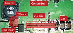
An intentionally bad layout helps illustrate the drawbacks of large current loops. Figure 1 shows a modified evaluation module (EVM) for the LMR23630 SIMPLE SWITCHER converter. Whereas the circuit’s two input capacitors should be as close as possible to the converter’s input pins, the modification deliberately relocates them about 2.5 cm from the input pins to simulate a bad layout.
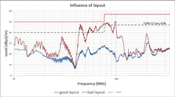
Figure 2 shows the results from the layout. The blue curve represents the properly laid out board, for which EMI remains within acceptable CISPR 22 limits. The red line represents the bad layout, for which EMI exceeds the relevant limits.
In addition to keeping the input capacitors close to the converter, you can help curtail EMI issues by keeping traces or cuttings in the ground plane to a minimum and protecting noise-sensitive nodes. For example, keep the trace from your circuit’s resistor divider to the converter’s feedback (FB) pin as short as possible (Fig. 3). A long trace here can couple electromagnetic disturbances into the FB pin, worsening EMI problems and potentially making your design unstable.
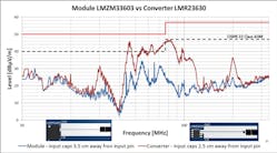
A power module helps simplify EMI mitigation. A comparison of a converter-based design with a power-module-based design illustrates the benefits of the latter. The converter-based design uses the TI LMR23630 converter, while the power-module-based design utilizes the TI LMZM33603 module, which incorporates the LMR23630 as well as an inductor and other passive components.
As was the case for the Figure 1 example, the EVMs for both designs have been modified to simulate a poor layout. For the converter-based design, the input capacitors have been moved 2.5 cm from the converter’s input pins; in the power-module-based design, the input capacitors have been moved 3.5 cm from the input pins.
As illustrated in Figure 4, the EMI of the converter-based EVM exceeds allowable CISPR levels. The power-module-based design is more forgiving of the suboptimal layout, and EMI remains within CISPR limits.
Beyond BOM Costs
Traditionally, modules have been more expensive than converters employing discrete inductors, but that’s changing because of advances in processes and materials. Indeed, the cost of the TLVM13630, a 3- to 36-V input, 1- to 6-V output, 3-A step-down power module, is about 75% lower than a similarly rated module introduced in 2010.
Consider as an example a 24-V input, 5-V output, 10-W design based on the TLVM13630. Compared with the similarly rated LM60430D buck converter, the TLVM13630 is about $1 higher in cost, and the complete BOM cost for the TLVM13630-based design is about 5% higher than for the LM60430D-based design.
However, it’s important to look beyond the BOM costs and consider PCB costs and design time as well. The TLVM13630 is about 30% smaller than the LM60430D and requires fewer external components, thereby saving PCB real estate, reducing layout complexity, limiting the number of vias, and minimizing potential sources of EMI. Although design time can vary, a module can reduce design time by almost half.
Conclusion
By choosing a power module that’s fully characterized for electrical, thermal, and EMI performance, you can eliminate the need for inductor selection, qualification, and sourcing. In addition, TI offers the resources you need for a successful design, including characterization data, WEBENCH simulations, and SIMPLIS or Spice models. These tools give you a head start in attaining the performance you need for your most stringent power-module use cases.
Sponsored Resources:


