Download this article in PDF format.
We’ve talked quite a lot about the new USB specifications in recent articles (see here, here, and here). One feature we haven’t covered in depth is Fast Role Swap (FRS), defined in the latest USB Power Delivery specification (USB PD) version 3.0.
Why do we need it? Picture this common scenario: You're hanging out in your Wagga Wagga apartment watching reruns of “Skippy The Bush Kangaroo.” Then the unthinkable happens. Your pet wombat (or puppy if you’re not Down Under) accidentally disconnects the power cord to the USB hub that’s supplying your laptop, screen, and wireless router (Fig. 1).1. An unexpected loss of USB power can have many causes. (Source: Sete Window Blinds)
Disaster looms. An end to your viewing pleasure is just milliseconds away.
FRS was designed to prevent such an event. It’s intended to keep the devices in a USB ecosystem powered when the hub they’re attached to loses power. This supports the vision of USB as a flexible and robust power-delivery system for low-voltage devices, with power coming from a variety of sources as appropriate.
In this article, we’ll examine in detail how FRS works to prevent an interruption of your “Skippy” experience, and a practical implementation of this feature.
The FRS Event: Before and After
An FRS-compliant port must be able to switch from sinking power to sourcing power quickly enough to avoid any interruption of power. The specification requires the hardware to respond to the power loss and begin sourcing power in under 150 μs. That’s not enough time to run through the standard USB Power Role (PR) Swap sequence.
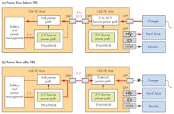
Before the power loss, initially, the USB PD Hub is sourcing power and the USB PD Host is sinking power. The voltage on VBUS can be as high as 20 V depending on the USB PD power contract that’s negotiated between the ports.
2. The USB PD Host and Hub switch power-delivery roles after an FRS event that’s initiated by the USB PD Hub’s charger becoming disconnected. (Source: Texas Instruments)
The Source pulls up the configuration channel (CC) line to 5 V with a resistor Rp, and the Sink pulls down the CC line to ground with Rd. The functions of Rp and Rd are defined in the USB Type-C specification: The value of Rp “advertises” (the word used in the specification) the current available from the source at the standard 5-V USB power line voltage. Then the Source power becomes disconnected, triggering a Fast Role Swap.
After FRS, the roles are reversed: the old Source is now the new Sink, and vice versa. The new Source provides 5-V power on VBUS and pulls up the CC line with the appropriate value of Rp. The new Sink supplies the pulldown Rd. Figure 2 shows the power flow before and after the FRS event.
Detailed FRS Sequence
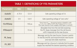
In the discussion that follows, parameters in this font are defined in the USB PD specification (Table 1).
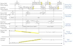
The Fast Role Swap sequence begins when the power source recognizes that it has lost power. The items in red refer to the complete FRS sequence shown in Figure 3. Numbers denote messages over the CC line and letters indicate other events.
3. Implementing an FRS requires a complex exchange of messages. (Source: USB.org)
Note that after each message is sent, the recipient first checks the cyclic redundancy code (CRC) and responds with a GoodCRC message if valid (this step is omitted from the list below):
1. The initial Source stops driving its power output (A), which starts transitioning to vSafe0V and signals FRS with a Fast Swap signal (B). It shorts Rp to ground on the CC line for ~100 μs.
2. The old Sink detects the Fast Swap (C) and stops sinking power. At this point, the new Source (old Sink) still has Rd asserted, and the new Sink (old Source) still has Rp asserted.
3. The old Sink and Source switch functions become the new Source and Sink, respectively. USB PD 3.0 allows the new Source to start applying power at any time after VBUS ≤ vSafe5V(max), but requires it to start driving VBUS (D2) to vSafe5V no later than tSrcFRSwap after VBUS ≤ vSafe5V(min).
4. Following the FRS, the new Source sends an FR_Swap Message (1) to the new Sink. This must occur within tFRSwapInit of detecting the Fast Swap signal.
5. The new Sink sends an Accept Message (3) in response to the FR_Swap message.
6. The new Sink asserts Rd (F) and sends a PS_RDY Message (5) indicating that VBUS ≤ vSafe5V.
7. The new Source asserts Rp (G) and sends a PS_RDY Message (7) indicating that it’s acting as a Source and supplying vSafe5V.
8. The power-delivery capability of the new Source is unknown at this point, so the Source and Sink negotiate a new USP PD power contract and adjust the voltage and current levels accordingly.
The TPS65983B USB PD 3.0 Controller
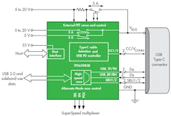
4. The TPS65983B has three separate power paths to accommodate various USB PD and non-USB PD use cases. (Source: Texas Instruments)
The TPS65983B is an example of a standalone USB Type-C and PD controller that includes Fast Role Swap in addition to standard functions such as cable detection, plug orientation, power negotiation, and Alternate Mode.
The TPS65983B has three independent power paths (PP), one external and two internal, for sourcing or sinking power (Fig. 4). Table 2 details each of these paths.
The TPS65983B digital core, power management, and USB PD physical-layer (PHY) blocks work together to support the FRS function. When the TPS65983B is operating as a Sink with FRS enabled, the TPS65983B monitors the CC pin voltage. If the CC voltage falls below the FRS request voltage detection threshold VFRSDETECT (= 520 mV typical), the FRS circuitry signals to the digital core. The TPS65983B ceases operating as a sink and begins operating as a source.
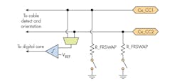
Conversely, when the TPS65983B operates as a Source with FRS enabled, the TPS65983B digital core can signal to the connected port partner that a FRS is required by shorting the connected CC to ground through the 5-Ω resistor R_FRSWAP (Fig. 5). The TPS65983B then ceases operating as the Source and begins operating as a Sink.
After receipt of the FRS message, the host must act very quickly. As we’ve seen, it has less than 150 µs to change from Sink to Source and provide up to 5 V at 3 A.
5. The TPS65983B contains pull-down resistors on the CC lines to signal an impending Fast Role Swap (Source: Texas Instruments)
Since the TPS65983B integrates both the source and sink power paths, it can dynamically change the switching time of the FETs in the internal power path to meet the FRS timing requirements. It also can dynamically reconfigure the current-limit circuit to accommodate the increased inrush current due to the quick turn-on time.
Multiport Adapter Reference Design with FRS Capability
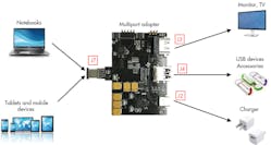
To evaluate USB PD Fast Role Swap as well as other USB Type-C features, Texas Instruments has included two TPS67983Bs in its TIDA-03027 multiport adapter for USB Type-C hosts (Fig. 6). The design features USB 3.0 data, video, and USB PD charging of up to 60 W (20 V/3 A) over a single, USB Type-C plug connection.
6. TI’s TIDA-03027 multiport adapter for USB Type-C hosts incorporates USB 3.0 data, video, and USB PD charging of up to 60 W. (Source: Texas Instruments)
In addition to the TPS65983B, the adapter contains a selection of USB Type-C system chips, protection, and power devices, including:
TUSB8041: 4-port SuperSpeed USB 3.0 hub
HD3SS3212: Two-channel differential 10-Gb/s multiplexer/demultiplexer
TS3USB221: High-Speed USB 2.0 480-Mb/s multiplexer/demultiplexer
TPD8S300: USB Type-C port protector with short-to-VBUS and ESD protection
LM3489: Hysteretic PFET buck controller
TPS62065: 3-MHz, 2-A step-down converter
TPD13S523: 13-channel HDMI port with ESD protection and current limit
Consult the TIDA-03027 design folder for more information.
The relevant multiport connectors are:
- USB Type-C plug (J7): A full-featured plug that allows a USB Type-C host (notebook or tablet) to interface with the data, video, and charging capabilities of the other ports. In the absence of a charger, the adapter power comes from the 5 V provided by the USB Type-C host. If a charger is available and has the drive capability, the multiport adapter can provide all of the USB PD 3.0 charging voltages (5/9/15/20 V) to the USB Type-C host.
- USB Type-C receptacle (J2): Allows the USB Type-C host to interface with USB 3.0 devices such as smartphones and flash drives. It also accepts USB Type-C power adapters to charge the host.
- HDMI 2.0 receptacle (J3): Allows the USB Type-C host to drive HDMI 2.0 monitors. The HDMI channel can switch between two- and four-lane operation depending on the capability of the devices connected to the USB Type-C and Type-A receptacles.
- USB 3.0 Type-A receptacle (J4): Allows the USB Type-C host to interface with USB 3.0 devices lacking a Type-C connector.
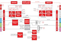
Figure 7 shows the internal block diagram of the multiport adapter.
7. Shown is an internal block diagram of the multiport adapter. (Source: Texas Instruments)
Evaluating FRS Behavior
A charger connected to J2 provides the power for the multiport adapter according to the USB PD negotiated contract. It also charges the USB host through J7, which is acting as a Source.
If the charger becomes disconnected, the TPS67983B port controller for J7 recognizes that it has lost power, sends the FRS message, and begins the process described earlier. The USB Host on the other end of the cable becomes the Source and the adapter power is uninterrupted.
Conclusion
One of the goals of USB is to provide a powerful and flexible low-voltage dc power-distribution system enabled by the USB Type-C standards, with multiple devices able to sink or source power as appropriate. USB PD 3.0’s Fast Role Swap feature supports this vision by allowing for seamless power transfer and continued system operation following an unexpected loss of power.
Texas Instruments offers USB port controllers that support FRS, as well as a multiport adapter reference design that will help designers get started with the new function.


