What Do Clocks, Carriers, Local Oscillators, and FM Have in Common?
Download this article in PDF format.
The master timing control circuit for most electronic applications is a precision signal source. For digital applications, it’s an accurate clock. In RF applications, it’s a carrier source for a transmitter or a local oscillator (LO) for a receiver. And if frequency modulation (FM) is involved, a modulator and demodulator are needed along with a carrier source.
In all of these cases, a phase-locked-loop (PLL) frequency synthesizer is an excellent choice. It provides not only the precision and accuracy needed, but also a flexible way to change frequency.
PLL 101
Just as a review, a PLL synthesizer is a closed-loop controller with feedback (Fig. 1). A voltage-controlled oscillator (VCO) generates the output signal. Frequency is determined by an LC resonant network, but controlled by a dc input voltage derived from a phase detector and a low-pass loop filter.
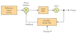
1. The basic configuration of a PLL features a VCO output, controlling circuits such as the phase detector, and feedback dividers.
The input to the phase detector is usually a stable reference signal from a crystal oscillator. The second input to the phase detector is a signal derived from the VCO output that’s usually divided down by a variable-frequency divider. The two inputs to the phase detector must be the same frequency.
The phase detector compares the stable reference input to the divided VCO output. If the output frequency should change, the phase detector recognizes the variation and produces a dc voltage change to adjust the VCO to maintain a constant output frequency. This closed-loop operation keeps the output frequency steady despite any variations. The output essentially has the precision and stability of the input reference.
To change the frequency, you adjust the divide ratio N. For example, if the VCO output is 480 MHz and you’re using a 1-MHz input crystal reference, you will need a divider that divides by 480. The divider is variable. Changing the division factor to 481 will produce a frequency and phase change recognized by the phase detector. As a result, the VCO output will be changed to 481 MHz.
Note that the output frequency changes in increments equal to the input reference frequency. That reference frequency can be varied by inserting a divider (and/or multiplier) between the reference oscillator and phase detector.
FM Modulation Methods
Frequency modulation has been around for over 80 years thanks to inventor and EE Edwin Armstrong. FM is a popular modulation scheme used to transmit information on a high-frequency radio carrier by varying the carrier frequency. It’s still widely used today in both analog and digital formats. You see analog versions in the form of FM broadcast radio or two-way mobile radio. You see it in digital form as frequency shift keying (FSK), like that in Bluetooth and some ISM band radios. In both cases, you will find PLLs involved.
There are a couple of FM implementation techniques, each with different characteristics. In general, you can generate FM in either an analog or digital way. Regardless of technique, you will need a frequency synthesizer to generate the high-frequency radio carrier.
One analog technique is to directly modulate the VCO. A common arrangement is to use varactor diodes (voltage-variable capacitors) to change the capacitance value in the VCO LC tuned circuit. Another method uses the modulating signal to modulate the reference oscillator. In this case, the reference isn’t a precision fixed-frequency crystal oscillator. It would be an LC oscillator whose frequency is changed by the variable capacitance of one or more varactors.
A digital method of modulating a PLL is to rapidly change the divider value. Switching between two divider values generates standard FSK. This approach can be used to generate 4FSK or 8FSK, which boosts bit rate by creating four or eight “symbols”; each symbol frequency represents multiple bits. Using 4FSK, with four frequencies each representing two bits, achieves a doubling of the data rate. With eight frequencies, three bits are represented per symbol.
A key factor in using FSK is to reduce the bandwidth of the transmitted signal by shaping the modulating signal. This is usually done by filtering the binary signal and rounding its edges, which has the effect of reducing the number of harmonics in the signal. This, in turn, reduces the number of sidebands produced by the FM signal.
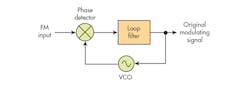
2. When demodulating FM, you just need a PLL with no feedback divider.
To demodulate FM, all you need is a PLL with no feedback divider (Fig. 2). The VCO is set to the carrier frequency and the FM signal is applied to the reference input. As the VCO tracks the input frequency variations, the loop filter output is the original modulating signal. Go here for more on FM.
PLL Specifications
When selecting a PLL integrated circuit, one needs to consider these key specifications:
- Frequency range: IC PLLs are available with frequency ranges from 10 MHz to 20 GHz.
- Phase noise: Typical figures depend on the specified offset from the carrier that can range from 10 kHz to 1 MHz. The rating is in dBc/Hz. An example is −110 dBc/Hz at 100 kHz offset.
- Jitter: Measured in femtoseconds (fs). Specified in rms at some frequency.
- Divider resolution: Commonly 32 bits with integer or fractional-N format or both.
- Ability to frequency modulate: FM, FSK, ramp/chirp.
- Synchronization capability to align the output phases of multiple PLLs.
- Adjustable delay capability.
- Low noise and noise floor: As measured in dBc/Hz.
If you’re looking for a PLL, consider Texas Instruments’ Microwave PLL and Synthesizer Brochure (PDF). It's a complete portfolio of RF PLLs and synthesizers that are applicable in industrial, communications, and automotive systems.
A Modern RF Synthesizer
An example of a common PLL IC is the TI LMX2594. It operates anywhere in the 10-MHz to 15-GHz range. Figure 3 shows a simplified diagram with the main system blocks. The reference input is differential and drives a divider/multiplier chain that provides flexibility in setting up the frequency step change increment. It also allows for adjusting the system to minimize the occurrence of spurs. The VCO output is buffered by differential amplifiers. In addition, the loop filter is implemented externally with discrete resistors and capacitors.
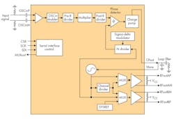
3. Shown is a simplified diagram of TI’s LMX2594 PLL. (Courtesy of Texas Instruments)
Some of the possible applications include 5G and millimeter-wave wireless infrastructure, test-and-measurement equipment, radar, MIMO, phased arrays and beamforming, and data-converter clocking with support for JESD204B.
This IC has advanced phase-synchronization capabilities that enable phase alignment of multiple RF PLLs. By using the SYNC pin, the reference input (OSCin) can be aligned deterministically with the RFout pins. This makes it possible to adjust the phase in very fine steps or divide the VCO period by a fractional denominator. It’s an essential capability for building systems with radar, MIMO, phased-array antennas, and beamforming.
You can learn more about advanced phase-synchronization capabilities with multiple RF PLLs by viewing TI's training video involving the high-performance LMX2594.
About the Author

Lou Frenzel
Technical Contributing Editor
Lou Frenzel is a Contributing Technology Editor for Electronic Design Magazine where he writes articles and the blog Communique and other online material on the wireless, networking, and communications sectors. Lou interviews executives and engineers, attends conferences, and researches multiple areas. Lou has been writing in some capacity for ED since 2000.
Lou has 25+ years experience in the electronics industry as an engineer and manager. He has held VP level positions with Heathkit, McGraw Hill, and has 9 years of college teaching experience. Lou holds a bachelor’s degree from the University of Houston and a master’s degree from the University of Maryland. He is author of 28 books on computer and electronic subjects and lives in Bulverde, TX with his wife Joan. His website is www.loufrenzel.com.
Comment About the Article
To join the conversation, and become an exclusive member of Electronic Design, create an account today!

Leaders relevant to this article: