
Download this article in PDF format.
Over 10 years ago, Bob Pease did a nice video about current sources:
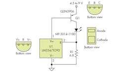
He described a circuit that used an LM334 current-source chip as the basis for an LED driver (Fig. 1). It’s a neat circuit, where the LM334 power pin draws from the base of a PNP transistor. This servos the current until the LM334 senses 0.068 V on its “R” pin. By putting in a 6.8-Ω resistor, Pease caused the current through the LED to be 10 mA.
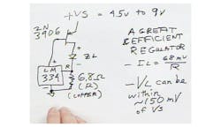
1. Bob Pease used an LM334 current source to servo the current from a PNP transistor through an LED diode. The LM334 will draw current into its V+ pin until the voltage on the R pin reaches 0.068 V. With a 6.8-Ω resistor, the current will be 10 mA through the LED, and one-hundredth of that into V+. (Courtesy of Andy Aronson, Texas Instruments)
To my dismay, a person left a comment on the video, “Schematic at 09:07 is wrong by far. Collector branch should be disconnected from the sensing resistor of LM334, and connected (through the LOAD) directly to Ground." Anyone who calls Bob Pease "wrong by far" needs to be on pretty solid ground. I think this person does not understand the nature of the circuit.
Perhaps the commenter saw this YouTube video that is wired the same way:
That circuit is sub-optimal as well. If you hook it up this way (Fig. 2), you are depending on the beta (current gain) of the PNP transistor to set the current in the LED. Different transistors of the same part number can have wildly different beta values.
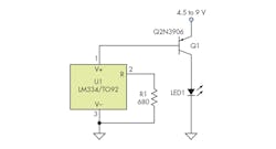
2. A commenter on YouTube said Pease was “wrong by far” and that the circuit should be connected this way. Unfortunately, the current in this circuit depends on the beta, or current gain, of the transistor.
The datasheet for the 2N3906 specifies a beta, or hFE, as a range of 100 to 300. If you do a production run of boards using this circuit, some of the LEDs could be three times brighter than others. The circuit as described in the comment is running open-loop. Beta also changes with temperature (Fig. 3). Contrast this with the 3% or 6% accuracy of the LM134/334.
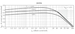
3. The current gain, also called beta or hFE, of the 2N3906 transistor also changes with temperature. (Courtesy of ON Semiconductor)
Be aware the LM334 is also a temperature sensor. Its output is PTAT (proportional to absolute temperature). Pease’s original schematic in Fig. 1 notes the 6.8-Ω resistor is formed from copper, perhaps a long, narrow circuit-board trace. This way the temperature coefficient of the chip and copper somewhat balance out. The LM334 datasheet also shows a way to add a diode and resistor to the chip circuitry to null out any temperature change when using discrete resistors instead of a copper trace (Fig 4).
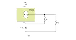
4. The LM334 datasheet shows how to add a resistor and diode to make the current source independent of temperature. (Courtesy of Texas Instruments)
To demonstrate the wonders of a servo system, I drew up a more helpful schematic (Fig. 5). It’s the same as Pease’s electrically, but I noted the pinouts of the parts so I could solder up a prototype using copper-clad and “airball” wiring (Fig. 6), something Pease was famous for.
5. I redrew Pease’s circuit, adding pinouts of the parts so I could solder up a prototype.
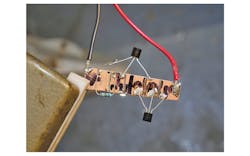
6. I soldered the parts to a small piece of copper-clad circuit board material. I ground slots in the copper to isolate the circuit nodes. The 1206 LED is on its side in the middle of the bottom edge of the board. I wrote helpful assembly reminders with a Sharpie directly on the copper.
LED Enlightenment
I wanted so see how modern high-efficiency LEDs worked, and those are all surface-mount devices. This design used an LED in a 1206 package. It was a little daunting soldering it down, as the terminals did not wrap around the ends like a 1206 surface-mount resistor. Instead, I soldered the LED on the side of the copper-clad board across a slot I milled in with a Dremel tool and cutoff wheel. It was delicate work, but having a Metcal soldering iron and a headband magnifier made it pretty straightforward. I soldered the LED first, so there was no other clutter in the way.
When I took measurements, I was amazed at how stable the circuit was over power-supply voltage (see table). The circuit has even more compliance than the 4.5 V claimed by Pease. It worked all the way down to 3-V input. Note that VR is measured to 100s of microvolts and is identical all the way down to 3 V. I wonder why Pease only showed the circuit working up to 9 V.
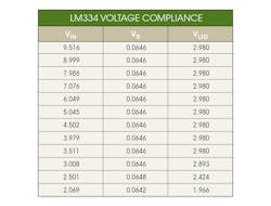
The output stability of the LM334 LED driver circuit is remarkable. The circuit keeps compliance down to 3-V input.
At high input voltages, the limiting factor will be the power dissipated by the transistor. The current through the transistor is 0.01 A. If the voltage across the transistor is 30 V, then power dissipation is 0.3 W. Don’t make a newbie mistake and think the 650-mW rating of the 2N3906 means it can dissipate 300 mW. The power rating declines with temperature.
The thermal resistance from the die to the air is 200°C/W. That means the 2N2906 will have a 60°C rise over ambient temperature when it dissipates 300 mW. The datasheet notes you have to derate the power capability by 5 mW for every degree Celsius. That’s 300 mW less. The derated power rating is 350 mW. The part should survive, but there’s little safety margin in the design.
Putting in a bigger transistor will not help unless that transistor has less thermal resistance to the outside air. Fact is, the die in the 2N3906 can carry the 10 mA just fine. It just can’t get the heat out. Note the same die is packaged in a SOT-223 surface-mount package as the PZT3906. The thermal resistance of that package is 125°C/W, so it would have a 38°C temperature rise. This package has a derating of 8 mW/°C. Therefore, we have to derate the power spec by 300 mW, the same derating as with the TO-92 package. The power rating of the PZT3906 is 1000 mW. At this temperature rise it can dissipate 700mW. That is a comfortable margin above the 300mW this circuit would dissipate with 30V across the transistor.
More Than Just a Footnote
There’s another “gotcha.” As someone who used to write datasheets, I can assure you the footnotes are there for a good reason. You have to read them as carefully as the specs themselves. On the PZT3906 thermal-resistance spec, there’s a footnote that points out the test condition is with the part soldered to 3- by 4.5-in. circuit board. The large collector pad on the part thermally connects to this slab of copper. If you don’t have an equivalent area, you might burn up the part. The footnote does not specify if thermal vias are taking the heat down to the bottom layer as well, but you might want to check this, carefully, before you release a design to production.
The LM334 datasheet also warns about self-heating. If you have 40 V across the part, it would be dissipating 0.4 W at its maximum current capability of 10 mA. That is impractical—not only would you self-heat the part, but you would burn it up. You can’t count on the thermal-compensation circuit of Fig. 4 to correct self-heating. The compensation depends on the LM334 and the diode being at the same temperature.
You might be able to somehow thermally couple the two parts, but it is better to just make the dissipation in the LM334 negligibly low. This is the beauty of Pease’s circuit. It uses the gain of the transistor to reduce the current through the LM334. After all, you can get the 10 mA out of the LM334 with a direct connection. This would only work at low voltages. Higher-voltage inputs would self-heat the LM334 and eventually blow it up at high-enough inputs.
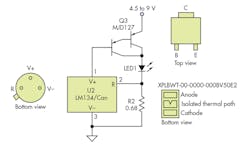
7. The circuit is super-sized to deliver 100 mA. It uses a Darlington PNP to supply the current to a super-bright LED. This circuit uses the metal-can LM134.
With an understanding of the thermal limitations, I still think the circuit could be pushed well past 9-V input. With 20 V across the transistor, it would dissipate 200 mW, and its derated power capability is 450 mW. That’s a pretty comfortable margin, at least as numbers on a page. The 40°C temperature rise would put the transistor at 65°C sitting in open air on your lab bench. That’s getting really close to being too hot to touch. It won’t sizzle and burn you, but it’s darn uncomfortable to hold your finger against for more than a second or two.
I did learn that Pease was a bit flippant when he said you could put in a 0.68-Ω resistor to get 100 mA through the LED. I set out to do that exact thing (Fig. 7). I used a Darlington PNP transistor to keep current into the LM334 minimal. I used a high-current, high-efficiency LED. It was surface-mount, so I used the same trick to solder it on its side to the hacked-up copper clad (Fig. 8). The LED did light, and these high-efficiency LEDs from Cree are amazing.
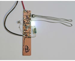
8. I soldered some bus wire on the Darlington transistor of a heat sink. The high-power Cree LED is soldered on its side and is quite bright. This board has an unused extra pad to allow for a temperature-compensation scheme as shown in Fig. 4.
Thing is, when I hung a scope across the resistor and LED, the circuit was acting like a relaxation oscillator, with a large spike in current every 0.6 ms (Fig. 9). I tried decoupling the circuit, I tried simple compensation, but nothing worked. The LED also brightened and then dimmed as the circuit went into compliance. I note some circuits in the LM334 datasheet use RC compensation. Maybe this circuit needs a pole added to stabilize the response. I thought I was starving the LM334 for current, since the Darlington has such high gain. A resistor in parallel with the base-emitter junction of the PNP transistor did nothing, so that’s not it.
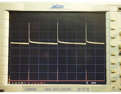
9. The high-current version of the design has an oscillation with a 0.6-ms period. The voltage across the sense resistor (red) and the voltage from the LED anode to ground (yellow) both exhibit this spiking. Upping the current with this scheme is not as easy as Pease made it sound.
I also blew up five LM334s; well, actually three LM334s and two LM134s, at 10 bucks apiece. Lesson learned. So there may be some oscillation occurring on power up, or maybe my lab supply is spiking when I turn it on. This shows even simple circuits with four components can be a real headache to troubleshoot and perfect.
I tried just doubling the current to 20 mA and that worked, but there was a small ac oscillation on the resistor voltage, so another instability problem. I ordered more parts, and will keep hacking on this circuit. The 0.68-Ω resistor I used was wire-wound, and that can turn linear circuits into switchers. Accordingly, I have some metal-film resistors on the way. I will keep you posted in a follow-on article.
This adventure shows the challenges, the horrors, and the delights, of analog engineering. Everything matters. Some things matter a little. Some things matter a lot. Some things matter to other things. And what matters will change over time and temperature and part-to-part variation. It’s a blessing and a curse. Try to enjoy the blessings so that those cursed circuits don’t drive you crazy.

About the Author

Paul Rako
Creative Director
Paul Rako is a creative director for Rako Studios. After attending GMI (now Kettering University) and the University of Michigan, he worked as an auto engineer in Detroit. He moved to Silicon Valley to start an engineering consulting company. After his share of startups and contract work, he became an apps engineer at National Semiconductor and a marketing maven at Analog Devices and Atmel. He also had a five-year stint at EDN magazine on the analog beat. His interests include politics, philosophy, motorcycles, and making music and videos. He has six Harley Sportsters, a studio full of musical instruments, a complete laboratory, and a video set at Tranquility Base, his home office in Sun City Center Florida.
Comment About the Article
To join the conversation, and become an exclusive member of Electronic Design, create an account today!

Leaders relevant to this article: