“Feeding The Hungry” with USB Type-C

Download this article in PDF format.
Remember the “good old days?” 1993, to be precise. Yes, we know that 1993 was the year of NAFTA and “Robin Hood: Men In Tights,” but that year also notched up several technological firsts: the first Pentium microprocessor; the birth of the World Wide Web at CERN; and the launch of IBM’s Simon Personal Digital Assistant, the world’s first smartphone.
It cost $899 and had a battery life of just one hour. Some would say we haven’t progressed much in the last two decades. Although its per-dollar performance has improved dramatically since 1993, the price for a top-end smartphone hasn’t seen a whole lot of change. And short battery life is still the biggest complaint of consumers.

1. Quality family time, 2017 edition. Pity those poor USB chargers (Source: nationalunplugingday.co.uk)
One feature that has changed is the charging method. Back in good old days, mobile phones had power plugs and dedicated chargers. Now almost all phones charge use the power pin of their USB port.
For a given charging current, the charging time of a battery is approximately proportional to its capacity. Over the last decade, smartphone manufacturers have steadily increased battery size (Fig. 2). All things being equal, a USB port will take twice as long to charge a Galaxy S8 as it will to charge an S1.
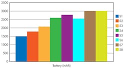
2. The battery of the Galaxy S smartphone has doubled in size since it first appeared in 2010. (Source: Author)
As the power and data requirements increased for USB-connected devices, the USB specification has tried to keep pace. The data rate has gone from 480 Mb/s (USB 2.0) to 10Gb/s (USB 3.1). The table shows the increase in maximum power for successive USB revisions.
USB 3.1 can supply up to 4.5 W using the familiar Type-A and Type-B connectors, but the USB Type-C connector allows up to 15 W. All three types (A,B, and C) supply 5-V power, but add USB Power Delivery (USB PD) compliance to the Type-C connector and the port can deliver up to 5 A at 20 V, or 100 W.
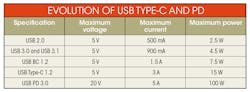
Successive revisions of the USB specification have steadily increased its power-delivery capability. Adding USB PD represents a quantum leap in power. (Source: Texas Instruments)
This makes it ideal for meeting the needs of a new generation of power-hungry applications that rely on USB power. “Feeding the Hungry,” if you will.
The USB Type-C Power-Delivery Vision
The USB Implementers Forum (USB-IF) is using this new capability to lay out a far-reaching plan for USB power delivery. It envisions USB Type-C and USB PD forming the basis of a powerful and flexible low-voltage dc network, in which interconnected devices can freely swap roles depending on which one has power available at any given time. These devices include those that up until now have consumed too much power to be powered from a USB port. Figure 3 shows the various elements in the USB Type-C landscape.
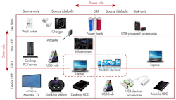
3. The new USB Type-C and USB PD specifications will accommodate a range of devices that were too power-hungry for earlier generations of USB. (Source: Texas Instruments)
When it comes to data and power flow in a USB Type-C/USB PD system, we no longer have fixed assignments—both the host and device can change roles, and so can the direction of power transfer.
We've covered the operation of the USB Type-C data channel in more detail here, and here. Briefly, though, for data transfer, the two functions "host" and "device" in earlier USB specifications are replaced by three Type-C functions: "downward-facing port" (DFP); "upward-facing port" (UFP); and "dual-role-data" (DRD).
A DFP, which sends data downstream, is typically the port on a host or hub to which devices are connected. A DFP also sources power, both to a device and to a Type-C electronically marked cable (EMC). A docking station is a typical DFP application.
In contrast, a UFP receives data from a DFP and usually sinks power. A monitor or solid-state drive (SSD) are examples of UFP applications.
As its name implies, a DRD can act as either a DFP or a UFP depending on the application.
When we add in USB PD compliance, there's a new set of terms to describe the direction of power flow. A USB PD port can be a power source and provide power over the VBUS pin on the Type-C connector; be a power sink and consume VBUS power: or be a dual-role-power (DRP) port that’s capable of both functions.
A Type-C wall charger is an example of a power source; a USB-powered peripheral such as a light or a fan is a power sink. A DRP can operate as either a sink or source, or switch between one state and the other.
When a DRP initially operates as a source, the port assumes the roles of a DFP for data. Conversely, when a DRP initially operates as a sink, the port takes the data role of a UFP.
USB Type-C System Blocks
Under the USB-IF’s new vision, a typical USB Type-C ecosystem (Fig. 4) contains a USB PD host, a hub, a charger, and one or more peripherals.
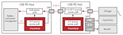
4. A USB PD Hub manages the power delivery to other components in the USB Type-C ecosystem. If no charger is present, the PD Host must supply power and the red arrows change direction accordingly. (Source: Texas Instruments)
The host, typically a laptop, server, or router, originates the data and controls the data transfer to the peripherals. Of course, the host may also have its own power source, such as a battery or charger.
The hub routes data from the host to the peripherals and distributes power to other units over a variety of connections: USB Type-C, other USB types, non-USB interfaces like HDMI or DisplayPort, etc. Since the host communicates over a USB Type-C interface, the hub must either contain a variety of dedicated interfaces or use USB Type-C Alternate Mode (AM).
The charger acts as a DFP and supplies the power level requested by the hub after the initial USB PD power contract negotiation.
Finally, the peripherals, such as an HDD or monitor, get their data and power from the hub. As mentioned earlier, the USB Type-C specification accommodates multiple non-USB protocols with its Alternate Mode specification.
The host in Fig. 4 has a DRP that can sink power to charge its battery, but can also source power to charge external accessories or power other devices. Moreover, the hub contains a DRP to source or sink power as needed. A DRP can change roles dynamically from a DFP to a UFP, or vice versa, by using USB PD Power Role Swap (PRS).
The standard PRS requires a negotiation procedure between the two ports to agree upon the power level (voltage and current) to be delivered. This is detailed in the USB PD specification. This may be too slow to prevent a power interruption in an emergency; for example, if the DRP powering a USB system unexpectedly loses charger power.
The latest revision of the specification, USB PD 3.0, therefore adds a Fast Role Swap (FRS) feature that allows a role change in 150 μs without negotiation. An FRS switches power very quickly, but uses default values for the new power levels to save time. Once the new source has taken over and power is stable, it triggers the standard USB PD negotiation.
Since the charger and the hub hold the keys to powering the new USB Type-C ecosystem, let’s examine a couple of reference designs as well as some key components needed to implement these two blocks.
USB Type-C Charger Reference Design
Texas Instruments has released several reference designs to help designers get started with USB Type-C charger development. In the Type-C ecosystem, the charger acts as a DFP and supplies the requested power level.
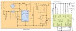
5. A simplified schematic of a USB Type-C charger includes an isolated flyback converter and a DFP source controller. (Source: Texas Instruments)
The PMP4489 reference design is a dedicated USB-C PD 2.0 DFP charger. The design operates from a 115/230-V ac input and provides a 5-V or 12-V, 3-A output. The main blocks are an isolated flyback converter with secondary-side regulation and synchronous rectification, and a USB Type-C port controller (Fig. 5). Below are some of its key components:
The UCC28740 forms the basis of the flyback power-supply primary-side circuit. This device is an isolated constant-voltage (CV) controller using optocoupled feedback to improve transient response to large load steps and a primary-side regulation (PSR) technique for constant-current (CC) regulation. This device provides precise high-performance control of output voltage and current.
On the secondary side of the transformer is the UCC24636, a compact, six-pin synchronous rectifier MOSFET controller. The device is designed to operate as a companion device to a primary-side controller and features a high-speed driver together with logic circuitry for an efficient synchronous-rectification system. The UCC24636 includes additional features such as pin fault protection, dynamic VPC threshold sensing, and voltage-sense blanking time for a robust solution.
The TPS25740/TPS25740A is a USB Type-C and USB PD Source Controller. It monitors the CC pins on the Type-C connector to detect when a USB Type-C sink is attached, and subsequently enables a N-channel MOSFET gate driver to turn on VBUS. The device then offers up to three different voltages using the USB PD protocol and selects the correct voltage from the upstream power supply based on the voltage requested by the attached sink.
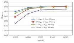
6. The PMP4489 reference design has high efficiency, particularly under high loads. (Source: Texas Instruments)
This reference design can achieve efficiencies greater than 90% under heavy load conditions, with an average of 89% under all conditions (Fig. 6).
The PMP20172 reference design demonstrates power management in a dual-port operation. The design provides up to 36 W on two USB Type-C outputs. If only one port is being used, it gets the full 36 W. However, if both ports are in use, the available power is split equally between ports.The circuitry for each port contains a TPS25740A that monitors the CC pins, as in the earlier reference design, and controls the output of a TPS40303 synchronous buck controller.
From a 17-V dc input, the design supports output voltages of 5, 9, or 15 V. With a 3-A output, the PMP20172 has a tested efficiency of 95% at 5 V, 97% at 9 V, and 98.5% at 15 V. It has been certified as a Power Brick by the USB-IF.
USB Type-C Adapter
The TIDA-03027 multiport reference design (Fig. 7) demonstrates many of the design concepts needed for a USB PD Hub. This design features a Type-C DRP plug that allows a USB PD host to simultaneously interface with USB Type-C (both chargers and peripheral devices), USB 3.0 Type-A, and HDMI 2.0 systems.
The design uses numerous devices in Texas Instruments’ Type-C product portfolio, but the key device for power transfer is the TPS65983B standalone USB Type-C and USB PD controller, which meets the latest USB PD 3.0 specification and handles power-delivery negotiations.
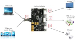
7. The Multiport adapter reference design lets the designer evaluate many USB Type-C functions, including Fast Role Swap and Alternate Mode operation. (Source: Texas Instruments)
As shown in Fig. 7, the reference design can demonstrate the full set of USB Type-C and USB PD power functions, including Fast Role Swap. It includes USB 3.0 Type-A and Type-C receptacles and an HDMI 2.0 receptacle to evaluate Type-C AM operation.
Review this earlier article for more information on this design.
USB PD Adoption
The USB Type-C connector will become ubiquitous over the next couple of years, but major manufacturers are designing in USB PD, too. In fact, both Apple’s 2016 MacBook Pro and Samsung’s Galaxy S8 are compliant. The USB PD adoption rate is expected to increase quickly over the next few years as well.
While it’s still early in the lifecycle of both USB standards, we can confidently predict that when we take a look back in 20 years at the notable technology events of the 21st Century’s second decade, both USB Type-C and USB PD will make the list.
About the Author
Paul Pickering
Paul Pickering has over 35 years of engineering and marketing experience, including stints in automotive electronics, precision analog, power semiconductors, flight simulation and robotics. Originally from the North-East of England, he has lived and worked in Europe, the US, and Japan. He has a B.Sc. (Hons) in Physics & Electronics from Royal Holloway College, University of London, and has done graduate work at Tulsa University. In his spare time, he plays and teaches the guitar in the Phoenix, Ariz. area
Comment About the Article
To join the conversation, and become an exclusive member of Electronic Design, create an account today!

Leaders relevant to this article: