Members can download this article in PDF format.
What you’ll learn:
- How the connector's unique interface enables it to support both AC and DC charging on the same pair of contacts.
- The communication protocols, safety features, and timing sequences used during AC and DC charging.
- Some of the challenges designers and manufacturers will encounter during the transition to this new standard.
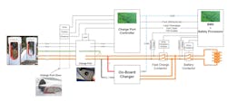
In Part 1, we introduced the SAE J3400 EV charging interface standard and Tesla's NACS connector that it's based on. As we mentioned, the specification includes a series of interlocks and safety protocols to ensure that only one power-delivery path can be active at a given time (Fig. 1). Both the SAE J3400 connector and the latest version of the Tesla charging interface, referred to as NACS (2021 and beyond), support vehicle-charger communications using the dual-mode powerline communication (PLC) protocol defined in the IEC 61851 standard.1
The first mode, known as Basic Signaling (BS), is the same pulse-width-modulation (PWM) scheme transmitted over the CP contact used by J1772 ac charging systems for safety-related functions and, in the case of ac charging, to advertise the power level available from the charging station.
The station can also transmit a pulse width of 5% that indicates the High Level Communication (HLC) protocol should be used. The HLC protocol involves transmitting a modulated high-frequency signal over the CP contact (also known as power-line communication or PLC) based on the standard DIN SPEC 70121 and the ISO/IEC 15118 standard3 that can be used to transmit digital commands and information.
Charging Event Sequence Overview
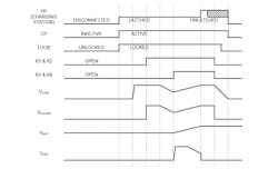
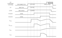
The charging system's hardware interlocks and control software guide the EV and its charging source through either an AC or DC charging cycle as described below. The DC charging (Fig. 2) and AC charging (Fig. 3) sequence steps includes all of the voltages and system elements.4
DC Charging Sequence Steps
t < t0: The operator signals their desire to initiate a charge session. If the vehicle is ready, the vehicle's mechanical interlock allows the connector.
t0 – t1: Once the vehicle connector is inserted into the vehicle, a lock is engaged to prevent its connector removal. Control Pilot communication is used to exchange initial charging parameters and verify compatibility. Once initiated, the lock remains engaged and digital communication remains active throughout the charge session.
t1 – t2: At this point, an optional internal isolation test may be performed on VCHG.
t2 – t3: Relays K1 and K2 close and an isolation test is performed between VCHG and VFCLINK. Note that power transfer is still inhibited at this point.
t3 – t4: The voltages VCHG and VFCLINK are adjusted to match VBAT.
t4 – t5: Relays K3 and K4 are closed, enabling energy transfer from the DC power source to the vehicle battery to take place.
t5 – t6: As VBAT approaches the desired level, S1 is opened momentarily or for a sustained period, or to indicate the charge session should be stopped and ICHG is turned off. For some vehicles, another prearranged signaling method may be used instead.
t6 – t7: Disconnection begins with K1, K2, K3, and K4 opened and VFCLINK being removed.
t > t7: Once electrical disconnect is verified, the mechanical lock is disengaged to allow the vehicle connector to be removed, thereby completing the charge session.
AC Charging Sequence Steps
t < t0: The operator signals their desire to initiate a charge session. If the vehicle is ready, the vehicle's mechanical interlock allows the connector.
t0 – t1: Once the vehicle connector is inserted into the vehicle, a lock is engaged to prevent its connector removal. Control Pilot communication is used to exchange initial charging parameters and verify compatibility. Once initiated, the lock remains engaged and digital communication remains active throughout the charge session.
t1 – t2: At this point, an optional internal readiness testing may be performed on the EVSE.
t2 – t3: K1 and K2 close and the onboard charger senses and matches the voltage of VFCLINK.
t3 – t4: The output voltage of the onboard charger is adjusted to match the voltage of VBAT.
t4 – t5: The EV's onboard charger initiates switching and energy transfer to the battery begins.
t5 – t6: As VBAT approaches the desired level, S1 is opened momentarily or for a sustained period, or to indicate the charge session should be stopped and ICHG is turned off. For some vehicles, another prearranged signaling method may be used instead.
t6 – t7: Disconnection begins with K1 and K2 open and VFCLINK being removed.
t > t7: Once electrical disconnect is verified, the mechanical lock is disengaged to enable the vehicle connector to be removed, thereby completing the charge session.
SAE J3400 Adoption Challenges and Timeline
In the long run, it’s rather certain that the industry, and its customers, will benefit from widespread adoption of the SAE J3400 charging interface. In the short term, though, progress will be slower and bumpier than one would hope due to several factors.
The issues surrounding adoption of the NACS/J3400 charging interface are complex enough to warrant their own feature story (or two). Electronic Design will be following these issues as they evolve so stay tuned for updates. For now, this section offers a summary of the biggest speed bumps on the road to NACS nirvana.
Since the initial version of the standard was not finalized until December of 2023, most manufacturers say that they will not be able to offer production vehicles with the new charging interface until later in 2024 and, in many cases, 2025.5
The other issue is that while Tesla has used the NACS-style connector for a long time, all of its pre-2021 vehicles communicated with Tesla charging stations using the CAN Bus protocol instead of the PLC scheme required by the NACS standard and the SAE J3400 spec. At present, this means that the large majority of Tesla's fleet of charging stations support CAN-based communications. Plus, there are provisions for CCS/PLC communications accomplished using a "Magic Dock" adapter that allows for an EV to charge with either an NACS or Combined Charging Standard (CCS) version 1 connector.
All of these issues add to the complexity involved with manufacturers' transition to SAE J3400, not to mention consumers' confusion. During this time of transition, it's expected that manufacturers will work around most of these issues using adapters that perform a function similar to Tesla's Magic Dock.
Future Prospects: V2G and V2X Integration Challenges
Furthermore, some remaining ambiguity in the protocols will eventually allow vehicles equipped with the NACS/J3400 connector to support vehicle-to-grid (V2G), vehicle-to-home (V2H) ,and other vehicle-to-everything (V2X) applications. In the absence of a definitive standard, companies currently offering vehicles with V2H/V2X capabilities (such as the Ford Lightning) are using home-grown proprietary signaling protocols.
That should eventually be resolved, but it's unclear whether EVs manufactured in the next couple of years can have these capabilities added via a software/hardware upgrade.
References
1. “IEC 1685,” Wikipedia.
2. “North American Charging Standard TS-0023666,” Tesla, 2022.
3. “ISO 15118-1:2019: Road vehicles — Vehicle to grid communication interface,” International Standards Organization (ISO).
4. “North American Charging Standard - Charging & Adapter Product Guides,” Tesla.
5. “The New Tesla / NACS Charging Connector Explained - The More We Learn, The Less We Know,” EV Buyers Guide, September 2023.


