What's the Difference Between CAN Bus and Automotive Ethernet?
This article is part of TechXchange: Time for Time-Sensitive Networking.
Members can download this article in PDF format.
What you’ll learn:
- Why the CAN bus technology has lasted nearly 40 years.
- Why evolving requirements of automotive electronics are outstripping CAN’s capabilities.
- How automotive Ethernet was developed to support the unique requirements of today's (and tomorrow's) highly computerized vehicles.
- How automotive Ethernet supports distributed real-time computing required for applications like driver assist, collision avoidance, and automated driving.
After nearly four decades, the Controller Area Network (CAN) bus, which made the rise of the modern "computerized car" possible, is being phased out in favor of more capable technologies, such as automotive Ethernet. Since its introduction in 1986,1 CAN bus has provided a highly reliable, low-cost means of communication for the electronic control units (ECUs) that lurk within nearly every element of a modern vehicle's drivetrain, body electronics, and infotainment system.
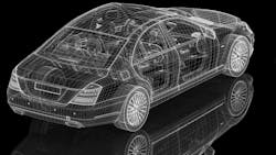
Although developed primarily for automotive applications, the low cost and high reliability of CAN bus has earned its widespread use in a startlingly large number of other applications that include agricultural equipment, avionics, industrial automation, elevators/escalators, railroads, and maritime systems (Fig. 1).
Recently, though, the higher data rates, lower latency, and faster response times required by advanced features, such as auto-braking, collision alert/avoidance, and various other requirements of autonomous driving, have far outstripped CAN bus's capabilities. Thanks to its superior speed, versatility, and ability to support time-bounded (isochronous) communications, automotive Ethernet has emerged as the most likely successor to CAN bus.
“The move to auto Ethernet has been driven by a number of factors, including open standards, multi-vendor solutions, and the ability to leverage network and protocol software that already exist in other industries where Ethernet deployment is ubiquitous,” said Ramin Shirani, CEO of Ethernovia.
He added, “The next generation of features available in a vehicle would only be possible with the introduction of automotive Ethernet to transport the exploding bandwidth to support these new applications, such as software-defined and autonomous vehicles, while providing accurate timing [IEEE802.1AS], security [MACSec], and guaranteed delivery of data [IEEE802.1 TSN].”
To understand why and how this evolution is occurring, let's take a look the two technologies’ capabilities, differences, and similarities.
What is CAN Bus?
CAN bus is a multi-master serial bus standard used primarily to connect ECUs, also known as nodes, in automobiles, trucks, and other embedded applications. The bus communicates across a single twisted-pair cable where the two conductors are referred to as CAN_Low and CAN_High. CAN bus supports a high-speed and a low-speed signaling mode, both based on a differential wired-AND signaling technique.1
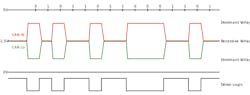
The high-speed mode is based on the ISO 11898-2 PHY standard, where the twisted pair forms a linear bus terminated at each end with 120-Ω resistors. In this configuration, both lines revert to a "recessive" state of 2.5 V (Logic 1) when they’re not being driven. When the wire pair is driven to its "dominant " state (Logic 0), the CAN_Low line is driven part way toward 0 V while the CAN_High line is pulled part way toward 5V.
In the dominant state, neither line reaches the supply-rail voltage, but the differential between the two lines provides a reliable indicator of the logic state. Depending on the length of the bus, the number of nodes, and other variables, high-speed CAN bus can support data rates of between 40 kb/s and 1 Mb/s (Fig. 2).
Low-speed (aka fault-tolerant) CAN is based on the ISO 11898-3 standard and supports data rates between 40 and 125 kb/s. It can use several different bus topologies, including linear bus, star bus, or multiple star buses. The low-speed signaling scheme operates similarly to high-speed CAN but with larger voltage swings that provide higher resistance to interference. In addition, the low-speed CAN bus enables communication to continue even if there is a fault in one of the two wires.
The dominant state (logic 0) is transmitted by driving CAN_High close to the device's supply voltage (5 or 3.3 V) while driving the CAN_Low line close to 0 V. In the recessive state, the termination resistors pull the bus to a logic "1" value with CAN_High at 0 V and CAN_Low at 5 V. This allows for the use of a simpler receiver that simply looks at the resulting polarity of the sum of CAN_High and CAN_Low.
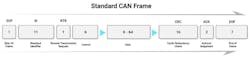
Both high- and low-speed CAN bus pass messages between nodes using a packet structure that includes an identifier/priority tag, a slot for the data being transmitted (up to 64 bits), and a checksum to ensure the data has been received correctly.2 Access to the shared medium is managed by a lossless bitwise arbitration method of contention resolution, as detailed in the ISO 11898-1 link-layer protocol standard (Fig. 3).1
Smarter Cars Demand Smarter Connectivity
For all its virtues, CAN bus has some limitations that won't allow it to meet the rapidly evolving requirements of today's vehicles. Most obviously, the levels of data traffic have surged far past the 1-Mb/s maximum rate supported by CAN bus.
Today's cars can use simple low-voltage differential-signaling (LVDS) links to transmit the high-speed video streams generated by a dozen or more body cameras feeding the ECUs that support driver-assist and autonomous-driving systems. However, the control signals and other intra-ECU messages they generate often exceed the capacity of a CAN bus.
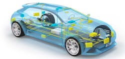
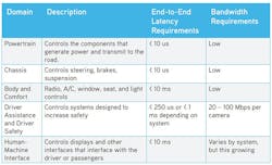
In addition, driver safety and automation systems require data and control signals to arrive in a timely and predictable manner. Many of these driver-assist and autonomous-driving functions rely on rapid interactions between multiple ECUs and their associated sensors. Thus, it became essential to ensure that the control and data messages they exchange occur predictably and have minimal delay—with maximum acceptable latencies sometimes measured in microseconds (Fig. 4).
What is Automotive Ethernet?
One of the most promising successors to CAN bus is automotive Ethernet, a variant of the ubiquitous family of 802.3 Ethernet standards, specifically adapted to the automotive environment. Among the most important requirements was to use a line coding scheme that’s virtually immune to the high levels of electromagnetic interference (EMI) present in many parts of the automotive environment.
In addition, it had to support communication across a single twisted-pair wire to minimize the weight of the network harness. Just as important, the transceiver electronics, and the wiring they communicate across, had to operate flawlessly across the full temperature ranges specified by standards ISO 16750-4 and AEC-Q100 (typically −40 to 125°C).
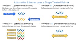
In response to the weight requirements, all variants of automotive Ethernet are based on a single twisted-pair wire used to support simultaneous transmit and receive operation, also referred to as full-duplex mode. Eliminating the second wire pair can reduce the weight of a vehicle's cable harness by as much as 30%, although it does have a potential drawback: Most versions of automotive Ethernet are limited to a maximum cable length of just 15 meters, though that’s more than sufficient for nearly all automotive applications (Fig. 5).
In keeping with the IEEE nomenclature rules, the common names for all automotive Ethernet variants based on a single twisted-pair PHY include the "-T1" suffix, beginning with the original 802.3bw (100Base-T1) interface. Since its introduction, the standard has been expanded to include 802.3bp (1000Base-T1) as well as 802.3.cg (10Base-T1S). Even faster data rates are available using the 802.3ch (2.5/5/10 Gbase-T1) standard, but it requires the use of shielded twisted-pair cabling for speeds in excess of 5 Gb/s to minimize EMI issues (see table).
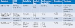
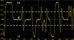
Both the 100Base-T1 and 1000Base-T1 versions of automotive Ethernet employ three-level pulse amplitude modulation (PAM-3) modulation, where each transmitted symbol is represented by one of three voltage levels.5 This signaling method is able to transfer 1.5 bits per clock cycle and increases the throughput for the same baud rate as bi-level signals. Other XXBase-T1 Ethernet standards that transmit at speeds in excess of 1 Gb/s use PAM4 signaling (i.e., with four logical levels), which increases throughput at the cost of decreased noise tolerance (Fig. 6).
For applications requiring longer cable lengths, the IEEE has introduced 802.3cz. It’s an optical PHY that supports data rates of 2.5/5/10/25/50 Gb/s for distances of up to 40 meters of graded index glass optical fiber.
To further reduce the amount of wiring needed in a vehicle, automotive Ethernet supports a IEEE -801.3bu, a new variant of Power over Ethernet (PoE) technology. The IEEE 801.3bu—1-Pair Power over Data Lines (PoDL)—Task Force has successfully introduced a standard for supporting PoE over a single twisted-pair wire with only minor modifications to the existing PoE standard.4
Auto Ethernet Delivers Extreme Real-Time Performance
In addition to raw speed, the automotive Ethernet standard incorporates several mechanisms to support precise real-time functions within the vehicle:
- The IEEE 802.1AS (Timing and Synchronization for Time-Sensitive Applications in Bridged Local Area Networks) standard is used to support algorithms that require either simultaneous sampling of multiple sensors or knowing the time that a measurement was taken. It enables synchronized measurements to be taken at different nodes with sub-microsecond precision5.
- Time-Triggered Ethernet supports control functions that require single microsecond communication latency. Instead of a new packet having to wait until an existing packet is complete, the IEEE 802.3br standard creates a system where high-priority packets (called Express packets) that can temporarily interrupt existing packets for immediate delivery.
- AV Bridging gives automotive Ethernet a two-part mechanism for streaming data packets from cameras and other sensors without interference and with a minimum of delay. 802.1Qat (Stream Reservation) is a simple reservation protocol to notify the various network elements in a shared data path to reserve the resources necessary to support a particular stream. 801.1Qav (Queuing and Forwarding for AV Bridges) defines the rules necessary to ensure that an AV stream will be able to pass through the network within the delay specified in the reservation.
Transitioning from CAN Bus to Auto Ethernet
Although CAN bus will probably continue to play a significant role in digital automotive systems for the next decade, automotive Ethernet's superior speed and ability to support precise time-critical communications will eventually displace it in most applications. This is especially the case with driver-assist and self-driving systems, where speed and predictable response times are essential.
During the transition, manufacturers will be able to deploy hybrid architectures using gateway devices to convert CAN messages to Ethernet either using UDP or IEEE 1722 as an encapsulation format. This means that OEMs can transition to an Ethernet-based network and still be able to connect to a legacy CAN ECU.
Read more articles in the TechXchange: Time for Time-Sensitive Networking.
References
1. "CAN Bus," Wikipedia Entry.
2. "Ultimate CAN Bus Guide 2023: A Detailed Look at the Protocol", 2023, AutoPi.
3. "Automotive Ethernet: An Overview," Ixia Communications, 2014.
4. "Single-Pair Power Over Ethernet," The Ethernet Alliance, 2020.
5. "Fundamentals of Automotive Ethernet,” Teledyne LeCroy, 2021.
About the Author

Lee Goldberg
Contributing Editor
Lee is the author of the popular PowerBites series.
Lee Goldberg is a self-identified “Recovering Engineer,” Maker/Hacker, Green-Tech Maven, Aviator, Gadfly, and Geek Dad. He spent the first 18 years of his career helping design microprocessors, embedded systems, renewable energy applications, and the occasional interplanetary spacecraft. After trading his ‘scope and soldering iron for a keyboard and a second career as a tech journalist, he’s spent the next two decades at several print and online engineering publications.
Lee’s current focus is power electronics, especially the technologies involved with energy efficiency, energy management, and renewable energy. This dovetails with his coverage of sustainable technologies and various environmental and social issues within the engineering community that he began in 1996. Lee also covers 3D printers, open-source hardware, and other Maker/Hacker technologies.
Lee holds a BSEE in Electrical Engineering from Thomas Edison College, and participated in a colloquium on technology, society, and the environment at Goddard College’s Institute for Social Ecology. His book, “Green Electronics/Green Bottom Line - A Commonsense Guide To Environmentally Responsible Engineering and Management,” was published by Newnes Press.
Lee, his wife Catherine, and his daughter Anwyn currently reside in the outskirts of Princeton N.J., where they masquerade as a typical suburban family.
Comment About the Article
To join the conversation, and become an exclusive member of Electronic Design, create an account today!

Leaders relevant to this article: