Building Home or Very Small Office Electronic-Circuit Prototypes, Part 1

This is hopefully the first installment of several related to setting up a small and inexpensive hobbyist/limited-technology-prototype build-and-test capability. I started this after my disappointment with a local maker shop in the Madison area. To be fair, this shop just moved and does not yet have much of an electronics contingent…yet.
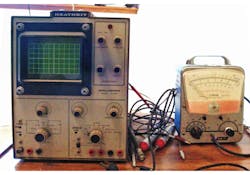
So why would I, an EE for 35+ years, suddenly be interested in such a small setup? Firstly, as was the case almost 45 years ago, I find myself again working out of my home and wanting to do simple prototypes and testing on-site. Over many years of employment, my original home lab setup that was used in high school to fix tube radios and TVs has, so to say, become “dated.” The old Heathkit 10-102 oscilloscope and Conar 211 vacuum-tube voltmeter (Fig. 1), assembled from kits, were okay in the 70s and 80s, but seemed a little weak for the tasks I needed to complete in 2015. Same for the National Semiconductor audio amplifier chip modified into a linear lab supply for 15 V and about 500 mA.
My employers for all of those years provided test and lab equipment, and technology changed from where a 5-MHz scope and an analog meter were fine, to where a digital meter, digital oscilloscope, and a “good” lab power supply have become minimum tools. Also, for a home lab, due to the huge changes brought about by miniaturization and surface-mount components, a reflow oven capability has become critical. Yes, I have hand-soldered 0402 resistors to a circuit board. After about the third or fourth resistor, especially for boards having 30+ small chip components, it starts getting really old.
At one of my prior employers, I used a Madell benchtop profiling IR/Reflow oven for building several circuit boards. There are two problems for using such a unit for home or maker environments:
1. The Madell units require 220 V ac to operate, and can consume a great deal of power. This generally means one must get (pay for) a special outlet for the 220-V power.
2. The Madell units are pretty expensive; the unit I used at work is similar to the current unit found at www.madelltech.com/SMD-2004A, listed at $2915.
So I went looking for alternatives. I found a website, www.whizoo.com, where a kit for modifying a small electric toaster oven to a temperature-profile-controlled convection reflow oven can be obtained, and bought their convection oven build kit. Whizoo called out an oven to modify that was listed, but out of stock at Walmart, so off to Amazon to purchase the same model…
The kit arrived with an Arduino ControlLeo-based digital display and control unit loaded with special firmware, materials for insulating the oven, a thermocouple temperature sensor, a small geared servo-motor to open the door for cool-down, an extra heating element, three solid-state relays, a 5-V power supply for the Arduino, and a bunch of miscellaneous parts for mounting, wiring, and general modifications to the oven. I have started putting this together.
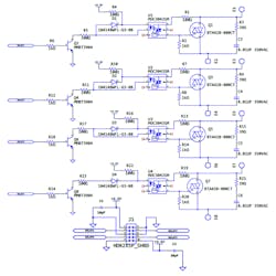
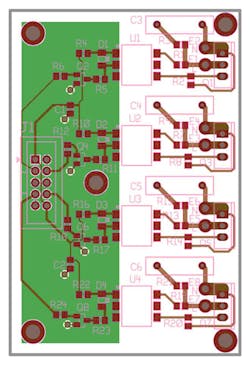
As I studied the kit, it occurred to me that a fair amount of the kit’s cost, and an ability to expand and modify the kit’s capabilities, was tied up in the use of solid-state relays. As always, going off on a tangent, I designed a circuit board to allow a 3.3- to 5-V digital system to control four ac outputs of up to about 10 A each. Figure 2 illustrates the schematic developed using PCBWeb Designer (a “free” package recently advertised by Digi-Key that I thought would be worth trying). Figure 3 is the board layout developed using PCBWeb Designer; the image from Gerbv displays the Gerber file data layers.
Lessons from the design included:
1. Free schematic-capture and board-layout packages are still somewhat more limiting than paid-for software. I have been tracking and investigating packages for many years (as a schematic design and board-layout software user since early 1990s), and can say the free stuff is improving. But don’t go into this expecting to have KiCAD or ExpressPCB/ExpressSCH or PCBWeb Designer jump to your every need, as well as Eagle, Altium, Mentor, or Cadence (or the numerous other vendor) offerings. Prepare for a learning curve and some possibly severe capability limitations, and be ready to create your own symbols and footprints libraries.
2. A well-advertised but relatively new package generally comes with several bugs, needed features, and a few glitches. Good news was, in the case of PCBWeb, they are in the project to make money, but not through standard and conventional means. It would seem they get payments by board makers and distributors (read Digi-Key) for their product being tightly tied to particular suppliers. As a result, when I found bugs and noted the lack of certain features in the early software, PCBWeb was very responsive and appears to be in process of fixing a lot of the normal early-release bugs, and adding needed features.
3. PCBWeb being tightly tied to vendors can have some advantages for a need-it-quick-and- cheap design project. The ties to Digi-Key seem very comparable to what some big-dollar software packages have done of late. It has full bill-of-materials (BOM) data-generation capability from the schematic-capture result, and even includes symbols and footprints for a limited number of parts. That’s not to say the symbols are ANSI standard (but the symbol provided can be modified or changed, or a custom part generated), nor that the footprints are what I might have generated with a $7K seat of Altium Designer or other similar package. Remember the article title, this is for low-budget and low time investment projects…
4. PCBWeb doesn’t yet generate the paste mask Gerber layer. I will be generating that layer by copying the top solder-mask layer to a paste-mask layer file, then editing the paste mask layer file to delete all through-hole mounting pads and all through-hole component pads. Then I will use a text editor to change the aperture sizes for the remaining surface-mount (SMT) pads so that the apertures are appropriately sized. The appropriate size for paste-mask openings is typically 2mils smaller than the copper layer pad, or 90% of the X and 90% of the Y dimension of the copper-layer pad, whichever is smaller. Some testing and tweaking will be appropriate as one learns the particulars for each package size and based on choice of thickness of the paste-mask material.
Referring back to Figure 2, the circuit shown provides four solid-state-relay-like control interfaces, with E1/E2, E3/E4, E5/E6, and E7/E8 as the controlled terminals for an ac device. A 3- to 5-V control signal and control power is provided into the 10-pin header supplied. The control signal turns on the appropriate transistor, which sinks about 2 to 5 mA from the control source. The current and voltage levels were chosen so that a microcontroller could directly control the signal. Note that the control signal must source current to activate a relay circuit, to ensure that the "totem-pole" or "CMOS" output configuration of the microcontroller will be appropriate.
Board Operation
I will describe one of the four circuits to clarify operation of the board, with the example calculations for 3.3-V operation. The computations are provided in parentheses to allow ready modifications if desired.
The second, third, and fourth control circuits are copies of the first (the designator numbers change, but operation stays the same). J1-3 is normally LOW, causing Q2 to be OFF, causing U1 LED to be OFF, causing U1 triac to be OFF, and causing Q1 to be OFF. When J1-3 is taken to 3.3 V with a 3.3-V supply at J1-1 and J1-10, 2.6 mA (3.3-V source minus 0.7-V Q2- B/E, divided by R6) flows into Q2-B. As a result, Q2 is saturated with a current of 9 mA (3.3 V minus sum of 1.25 V on LED and 0.2 V on Q2, divided by sum of R4 and R5) to drive U1 LED ON. This causes the U1 triac to turn on and stay on until the next zero crossing, where U1 LED is OFF.
With U1 triac ON and dropping about 1.8 V, R1 pulls the gate of Q1 ON whenever the voltage across E1/E2 has magnitude greater than about 9 V (at 35-mA gate threshold, 0.7 V to Q1-G and 6.3 V across R1 and 1.8 V across U1-triac). R3 and C3 provide some degree of noise snubbing.
Several points are worth discussing on circuit design and operation:
• Note the pinout of J1 is completely symmetrical. This makes it much harder to accidentally break stuff by installing or wiring the connector backwards.
• Although the turn-on current threshold for U1 is specified at 5mA, a value closer to 10 mA considers such things as operating temperature and LED device aging.
• R4 and R5 are “split” so that noise generated in the ac side of the optoisolator returns in a balanced fashion to ground, to minimize the effect of coupled noise on the 3.3-V power circuit. Likewise, the transistor and R6 significantly reduce noise into the logic circuitry.
• D1 provides “last ditch defense” of the LED in the case of reverse-polarity wiring, and provides additional protection for the LED and circuit operation from reverse-coupled noise. This was a trick learned years ago in the 100-V/m RF susceptibility room. Those who “harumph” at the extra cost are welcome to depopulate this diode, but don’t come crying about flaky operation or noise-related damage/degradation if you do. You will save a whole 10 cents on a prototype build.
• Triac resistors are sized for 120-V ac rms operation. See the datasheet for U1 to change R1 and R2 values to allow for 220-V ac rms values. The semiconductor components chosen should handle both 120-V ac and 220-V ac operation.
• Repurposing of one or more channels from ac triac control to dc control can readily be achieved by substituting the repurposed channel triac with a MOSFET or BJT, substituting the channel triac-output optoisolator with a transistor-output optoisolator, and adjusting resistors for proper biasing of the transistor. Note that pinouts for the optoisolator and the output switch device may change in the process. On brief review, it was found that the Fairchild H11F1SM has a matching pinout to the triac optoisolator for a <30-V control load. The triac pinout seems to be reversed from a MOSFET or BJT pinout for TO-220 (e.g., triac pins 1 and 2 are T1 and T2, and pin 3 is gate, standard MOSFET and BJT pin 1 is gate/base, pin 2 is drain/collector, and pin 3 is source/emitter).
This circuit should allow for replacement of up to four solid-state relays to control such things as the reflow oven or other small appliances or ac devices, and the BOM parts-only cost for one board is a whopping $17. The board layout is shown in Figure 2. The board measures 2 × 3 inches, double-sided. Such boards can be acquired for less than $11 each in quantities of 10 using the sources in PCBWeb, and $30 for 3 ($10 each) from OSH Park.
Hand-soldering is possible, as this design uses 0805 resistors and caps, and 100-mil-pitch gull-wing optos. Should a solder mask for SMT be desired, a 5- × 5-in. Mylar or Kapton mask for this board would run $50 from Stencils Unlimited (among others), less if a maker shop nearby has a laser cutter, and be useful for around 100 PCBs. A heat sink should be mounted to the triacs; to keep the overall size small, a small forced-air unit would be preferable. One possible unit might be:
www.amazon.com/Slotted-Aluminum-Radiator-Heatsink-80x40x40mm/dp/B00UJ97B4U (about $8)
with a 40-mm, 5-V fan like the:
www.amazon.com/RUNDA-4010-0-18A-2Wire-Cooling/dp/B0148GCTU0 (about $7).
Also, 25-A, single-form A, solid-state relays like those shipped with the kit from Whizzo run about $25 each from Digi-Key. The over-rating is chosen to better handle heat and minimize the heat-sink size and cost, even though the load for the highest relay is only 8 A or less.
Of course, this is a preliminary design, so I expect to be building a prototype in the next few months and doing some testing—a topic for future blogs.
About the Author
RWatkins
Consulting Engineer
Roger Watkins is an Ex-Navy Submarine Officer, having completed Submarine Officer and Submarine Nuclear Engineer qualifications. He has consulted, designed electronics, written software/firmware, searched patents, and managed design teams for several companies over many years, including:
- Analysis & Technology Inc. (acquired by Anteon International, today part of General Dynamics Information Technology)
- Lake Shore Inc. (today Oldenburg Group Inc., Defense)
- Caterpillar Inc.
- Quill & Disc Inc.
- Validus Technologies LLC
- bb7
- Intellihot Green Technologies
Comment About the Article
To join the conversation, and become an exclusive member of Electronic Design, create an account today!

Leaders relevant to this article: