What exactly is the function of the air gap? When asked this question, most engineers respond, “It prevents core saturation.” Although this may be true in certain cases, it's not true in general. In fact, in a transformer, the air gap will not prevent saturation caused by excessive ac voltage polarization, as we will see. Further, the air gap has several other critical functions.
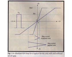
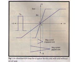
Fig. 1 shows two idealized B/H loops for a typical Ferrite core. The steep slope (high permeability) is for a core without an air gap and the more gradual slope for the same core with a small air gap. To start, we will assume the core is to be used for a high frequency transformer or an inductor. (A transformer or inductor, is only polarized with ac, while a choke or fly-back transformer has both dc and ac current components).
If we assume that the core size, primary turns, and frequency are predefined, the vertical scale B (flux density, Tesla) is proportional to the applied voltage (Vin) (you may prefer to think of it in terms of volt seconds). For this example a square wave voltage (Vin) is to be considered. This is shown to the left of the diagram. Notice that when the peak value of (Bm) is projected right so as to intersect with the non-gapped and gapped B/H loops, the margin between the peak working point (Bm) and the saturation value (Bsat) remains the same with or without the air gap. Hence, if the applied voltage were to be increased to the point of saturation, introducing an air gap wouldn't help.
In the case of a transformer or inductor, the air gap only reduces the slope of the B/H loop, reducing permeability and inductance, and hence increasing the magnetizing current in the primary. Remember that magnetizing current flows in the primary — even if the secondary is open circuit.
The horizontal scale H (magnetizing force, Oersted) is proportional to current when the core size, permeability, and turns have been defined. The increase in the magnetizing current between nongapped and gapped cores is clearly shown by projection from the intercepts on the B/H loops. Thus, in the transformer example, the gap is used to reduce the inductance (perhaps for resonant applications). In some cases, a very small air gap may be used in a transformer to define the primary inductance and reduce manufacturing variations. Keep in mind that the gap will not prevent saturation in true transformer applications.
In continuous conduction chokes, flyback “transformers,” and single-ended forward transformers, the function of the air gap is different (flyback transformers are really chokes with extra isolated windings).
In choke applications, we normally know the dc current (typically, the mean dc load current applied to the output filter in a switchmode power supply).
Looking at Fig. 2, you can see one quadrant of the previous B/H loop for a ferrite core, with and without an air gap. We enter this with the known parameter (dc current) on the horizontal scale, H.
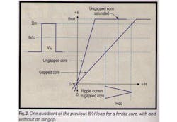
By projecting this upward, the gapped core intercept at Bdc is not saturated, while the nongapped core intercept (top line) is well into saturation (at Bsat). Therefore, the first action of the air gap in this application is to prevent saturation (it also changes the permeability and hence the inductance as well).
Because we normally know the applied ac voltage stress on the choke, we can apply this to the vertical scale, B, using the dc flux line (Bdc) as the mean value. This is set up by projecting to the left the intercept of the dc value of H on the gapped B/H loop, as shown. Notice that the maximum value of flux density (Bm) is now the sum of the dc and ac values, and it is much nearer saturation; a larger gap would be preferred. The projection of the ac component back to horizontal scale H shows the ripple current. Remember that increasing the air gap further will reduce the flux density generated by the dc current, but won't reduce the peak-to-peak ac flux change, as this is a function of the applied voltage. If you try drawing it, you'll see that the mean flux density will reduce while the peak-peak ac flux change will remain the same (notice that the peak-to-peak ripple current will increase).
Finally, even discontinuous forward designs will benefit from an air gap, as the residual flux value will be nearer zero, allowing a larger working flux density range.
Keith Billings is President of DKB Power Inc., ([email protected]), and author of the Switchmode Power Supply Handbook published by McGraw-Hill. He presents Abe Pressman's “Modern Switching Power Design Course” as required. For more information, visit the Web at www.apressman.com
For more information on this article, CIRCLE 339 on Reader Service Card
About the Author
Comment About the Article
To join the conversation, and become an exclusive member of Electronic Design, create an account today!

Leaders relevant to this article: