Reliability Design Guide for High-Voltage Capacitors
Over the last 40 years, a series of misconceptions regarding mica capacitor applications has led novice users to consistently over-derate wound or rolled mica/epoxy dielectric capacitors.
Mica, K2A13(Si04)3, a complex aluminum silicate in dielectric form, has been successfully used for many years as an integral part of high-voltage (2-kVdc to 50-kVdc) capacitor manufacturing, particularly in the 50-pF to 5-µF value range. The mineral term “mica” refers to a family of geological forms whose crystals exhibit a laminating-type structure, which allows it to be cleaved into thin sheets that are structurally strong, flexible, chemically inert and transparent. Mica has unrivaled physical and electrical properties in comparison to other capacitor dielectrics, especially ceramic. Mica also is extremely stable. Capacitance will change only -2% at -54°C, and to +3% at +125°C. Mica is an excellent insulator, and is resistant to high temperature, thermal shock, mechanical shock and vibration.
From Mica Mines to Paper
The mined mica is cleaved and baked-out to remove earth moisture and any combustible materials. A cleaning process using an acid follows the bake-out. The acid is then neutralized and the mica is rinsed with deionized water. Next, a pulverizing process converts the cleaved mica into microplatelets, typically in the 0.01-mm to 0.1-mm range. These platelets are then mixed with de-ionized water to become a pulp. The mica pulp is converted to a paperlike material using processes similar to bond paper manufacturing ranging in thickness from 0.018 mm to 0.05 mm (0.007 in. to 0.002 in.). Resulting from this process is a paperlike material that has no binders and is held together only by Van der Waal's forces.
The mica now can be wound, in combination with capacitor-grade aluminum foil, and then epoxy impregnated to become high reliability, reconstituted mica capacitors. A typical reconstituted mica capacitor is comprised of approximately 85% mica, 14% epoxy impregnant material and 1% capacitor-grade aluminum foil. These ratios can vary slightly with respect to capacitance range and voltage capability.
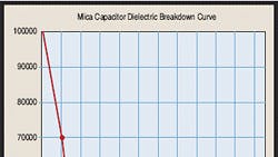
Reliability is directly related to electrical field stresses through the mica/epoxy dielectric structure. An assessment and derating, in volts per mil (0.001 in. or 0.025 mm), can be discerned from the industry standard, 1250 V to 1330 V per mil, operating, for greater than 100,000-hr mean- time-to-failure (MTTF) applications (see Fig. 1).
The dielectric stress, in volts per mil, for established reliability applications is selected to be below the dc corona (partial discharge) extinction voltage at the normal working voltage for the unit. This stress level is in the region of 1500 Vdc, with inception voltages in the area of 2000 Vdc for a well-made industry-standard capacitor. AC corona inception is approximately 700 Vac at 60 Hz, irrespective of the dc rating of the device.
When corona is present on a continuous basis, the life of the capacitor is dramatically reduced because of the fundamentally different wear-out phenomena as compared to operating inside the corona inception boundaries. Extrapolation of experimental results across the corona inception/extinction boundaries is not applicable.
To provide a high level of confidence in the reliability of any capacitor, a manufacturing screening procedure is desirable. This screening removes early failures (the so-called infant mortality group) from the lot without degrading deliverable components. Dielectric withstanding voltage screening is usually performed according to the schedule in Table 1.
The Table 1 test schedule is generally followed by a burn-in at a voltage that is at a midpoint between the dc-rated voltage and the dc test voltage. For example, a 15-kVdc capacitor should be burned-in at 18 kVdc. A burn-in is conducted at the operational temperature of the device. Burn-in schedules typically range from a few hours for noncritical applications to a week for satellite platforms.
An example of this misconception is: Given an application for a capacitor of 50 nF at 10-kVdc working/operating voltage, a capacitor can be designed within the approximate dimensions of 3.5-in. × 3.5-in. × 0.25-in. (volume=3.0625 cu.in.) with a dielectric thickness of 8.0 mils. While operating at 10 kVdc, this capacitor, which is at an electrical field stress of 1250 V per mil (10 kVdc/8 mils = 1250 V per mil), can be designed and expected to work for >100,000 hours without failure, assuming that correct epoxy impregnation processes have been used. A circuit designer usually has either in-house or customer-driven mandates to derate his product, sometimes by a factor of 60%.
Consider then the recalculation required to reassess the volume necessary to fill this derated application: 10 kVdc/0.6 = 16.67 kVdc rating in order to meet this mandate. A design to produce this revised capacitor will increase the size of the device to 5-in. × 5-in. × 0.36-in., with a volume of 9.0 cu. in., and will require an increase in the thickness of the dielectric to 13.5 mils. Again, while operating at 10 kVdc, this capacitor will be functioning at an electrical field stress of only 741 V per mil (10 kVdc/13.5 = 741 V per mil stress). Not obvious to the uninitiated, the voltage squared function (CV2/2 stated in joules) has produced a capacitor that has a volume/energy multiplier of 2.939 times that of the previous non-derated capacitor. This unnecessary over-derating causes useful volume to be wasted without any benefit of electrical performance, as shown in Fig. 2.
Fig. 2:This is an example of fitting a new mica capacitor assembly to replace an assembly of printed circuit boards filled with “less than reliable” ceramic capacitors. Mica capacitors can provide reliability far surpassing that of the usual ceramic package and can occupy nonrectilinear volumes. (graphic unavailable)
A mica dielectric capacitor should be specified by actual working voltage, which is the actual voltage at which the circuit functions during its operational life, not at a derated voltage. The mica capacitor also can be specified in not-to-exceed n volts per mil terms. Both methods of specification allow optimum design volumes to be used. A range of 1250 V to 1330 V per mil is recommended for more than 100,000 hr of reliable operation in normal filtering applications. Mica surpasses ceramic and film-type capacitors when temperature, capacitance stability and deep current discharge stability are a concern. Ceramic capacitors can operate at high temperature but exhibit undesirable characteristics, which may allow less capacitance than the circuit requires. High-current discharges are also an enemy of ceramic capacitors. Many film-type capacitors start to lose their effectiveness in applications above 85°C.
Alternate short-term reconstituted mica applications are capable of operation within an alternate set of design rules or industry standards, ranging up to approximately 1700 V per mil in some cases. Other variants of mica and man-made film capacitors exist, usually known as hybrid dielectric systems, which can operate at levels to 2000 V per mil.
Reliability test data has been accumulated for various system thicknesses over 540,000 hr of operation at a temperature of 125°C. This data is shown in tabular form in Table 2.
Wound mica capacitors have operated in military and commercial applications for more than 40 years. Application examples for reconstituted mica capacitors are: power-supply filtering (military and commercial); energy storage with high-current discharge (tactical missile); oil field well logging (case perforation); voltage multiplier (military, commercial, space); university and national laboratory (R&D [high-energy physics through rapid high-current discharge]); and baggage X-ray systems.
For more information on this article, CIRCLE 332 on Reader Service Card
Comment About the Article
To join the conversation, and become an exclusive member of Electronic Design, create an account today!

Leaders relevant to this article: