
The Circuit Designer’s Companion (Edition 4) by Professor Peter Wilson (University of Bath, UK) could have been entitled “Introduction to the Real-World of Electronic Design.” The information content is very good, my only suggested change would be to rearrange the chapters. That is, I wouldn’t make Grounding and Wiring the first chapter. I would start out with active and passive components and then include the rest of the chapters.
This book bridges the gap between the theoretical engineering that most university courses provide and the practical knowledge and application that comes from years of experience. The book is ideal as a refresher for current electronics design engineers, an introduction for advanced amateur electronics designers, and a reference for professors looking for a book with a real-world design outlook. In particular, it would be a good choice for recent engineering college graduates, either in electronics or other associated branches of engineering.
In his introduction to this fourth edition, Professor Wilson noted that there has been an explosion in “maker” projects since the third edition of the book. “Now there are UAVs, robots, autonomous systems, mobile electronics, 3D printing, which has also required a similar level of creativity and capability in electronics. Industry has also kept moving at an incredibly rapid pace, and yet university or college students still are not exposed to many of the practical skills and techniques that engineers tend to accumulate over many years.” This book fills in the additional information.
Chapter 1, Grounding and Wiring, points out that grounding techniques can impact electronic circuits of all kinds.
The book advocates single-point chassis connection that eliminates possible “ground loops,” a source of low-frequency magnetically induced interference.
Another technique picks one point in the circuit for all ground returns. Known as the “star point,” it can also be used as a local sub-ground point on printed circuit layouts.
Related to grounding is the use of various types of cables and their characteristics, including:
- Twisted pair, an effective and simple way for reducing both magnetic and capacitive interference pickup.
- Crosstalk that occurs when more than one signal is located within the same cable bundle. Mutual coupling between the wires can cause one signal to be fed into another and vice versa.
- Characteristic impedance (Zo) is an important parameter for a transmission line whose geometry and materials determine its dynamic value, independent of line length.
Chapter 2, Printed Circuits, describes the electrical and mechanical characteristics of a p.c. board (pcb). A pcb employs an insulating dielectric laminate of epoxy glass or phenolic paper. A conductive layer on the laminate is usually copper foil, adhesively bonded to the substrate. The required circuit is then etched in the copper foil. Boards have a common designation of “FR4,” which refers to the NEMA specification for flame-retardant epoxy-woven glass board. Boards may be:
- Single-sided
- Double-sided
- Flexible
- Double-sided PTH
- Rigidized flexible
- Multilayer with several layers of base material laminated into a single unit
- Flexi-rigid multilayer boards with some rigid layers
Plated-through holes (PTHs) for components on a board should be closely matched to the component’s lead diameter. However, some capacitors and power rectifier diodes may require larger holes.
Components may be mounted on board by:
- Plated-through holes, which accept components with lead wires.
- Surface-mount, where devices have termination areas held in place only by solder between pads on the board and their terminations
Thermal management includes three main methods for removing heat from a pcb:
- Convection
- Conduction
- Radiation
Convection and conduction are controllable methods for removing heat from system components. This is necessary because component-generated heat can radiate to other components and affect reliability.
In Chapter 3, Passive Components, the book describes resistors, capacitors, and inductors. Resistors may be taken for granted, as long they are operated within their power, voltage, and environmental ratings. However, there are applications where specifying and applying resistors needs to be handled with some care. Fixed-value resistors can be classified according to their construction:
- Metal film
- Carbon
- Wirewound
In addition, there are variable resistors such as potentiometers, rheostats, and trimmers. Plus, there are resistor networks with multiple resistors. There are also classes of resistors for high-precision, high-voltage, and low-voltage applications.
Important resistor characteristics are:
- Tolerance
- Temperature coefficient
- Power rating
- Inductance
There are many capacitor types that you can classify by their dielectric:
- Film: Polyester, Polycarbonate, Polypropylene, Polystyrene
- Paper Ceramic: Single layer, barrier layer, high-K, low-K
- Multilayer: COG, X5R, X7R, Z5U
- Electrolytic: Nonsolid and solid aluminum, solid tantalum
Important capacitor characteristics are:
- Leakage
- Ripple current
- Equivalent series resistance (ESR)
- Temperature rating
- Lifetime
- Dielectric absorption
- Self-resonance
Most inductors are made by winding wire around a magnetically permeable material whose characteristics, along with the wire’s dc resistance, determines inductor performance. There are also chip inductors that are manufactured using semiconductor material. General specifications for chip inductors include technology, core material, packing method, and application.
Among important wire-wound inductor characteristics are:
- Permeability
- Leakage
- DC resistance
- Self-capacitance
- Winding losses
Chapter 4, Active Components, covers diodes, thyristors, triacs, and bipolar transistors and IGBTs. In addition, there are descriptions of power MOSFETs and also wide bandgap (WBG) devices.
This chapter concentrates on discrete semiconductor components that are widely used in electronics design. Although there is a continuing trend toward “gathering up” discrete semiconductors into application-specific ICs, and a parallel trend toward replacing as many analog functions as possible by digital signal processing, discrete analog circuits are still needed when these solutions are impossible or uneconomical. It is as well to be familiar with the characteristics of practical components as even when integrated they show the same fundamental properties.
Added to this edition of this book is a section on gallium nitride (GaN) and silicon carbide (SiC) wide bandgap devices that exhibit significant performance improvements over silicon devices. Professor Wilson says that despite the intrinsically higher wafer costs, he expects the prices will continue to drop as more products enter the market, and a wider range of manufacturers develop competitive devices. An interesting challenge for designers wishing to use SiC or GaN devices in the future will be to develop effective gate drive circuits that will be designed to manage the much higher switching frequencies that are possible with both SiC and certainly with GaN devices.
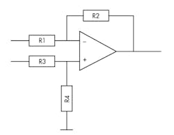
1. Basic Differential Op-Amp
Chapter 5, Analog Integrated Circuits, describes the operational amplifier as the basic building block for analog circuits and also devotes space to comparators and voltage references (Fig. 1). A discussion of op amp parameters includes:
- Offset Voltage
- Output Saturation Due to Amplified Offset
- Offset Drift
- Common-Mode Effects
- Common-Mode Rejection Ratio
- Power Supply Rejection Ratio
- AC Parameters
- Slew Rate
- Large-Signal Bandwidth
- Small-Signal Bandwidth
- Settling Time
- Open-Loop Gain
- Noise
The author looks at the departures from the ideal op-amp parameters that are found in practical devices and surveys the trade-offs including cost and availability, as well as technical factors that have to be made in real designs. Some instances of anomalous behavior are examined.
Comparator details include:
- Output Parameters
- AC Parameters
- Overdrive
- Hysteresis
Different types of voltage references are described:
- Zener References
- Bandgap References
The author points out that there is an obvious trade-off between initial voltage tolerance and temperature coefficient on the one hand, and cost and availability on the other, since the manufacturer has to accept a lower yield and longer test and trim time for the closer tolerances. Initial voltage can be trimmed exactly with a potentiometer, but this method adds both parts and production cost, which will offset the higher cost of a tighter tolerance part. Trimming the reference voltage can also worsen the reference temperature coefficient in some configurations.
Chapter 6, Digital Circuits, covers devices from logic ICs to microprocessors. Digital techniques eliminate the unpredictability and variability of analog, or linear circuits, including voltage drifts, component tolerances, offsets, and impedance inaccuracies that are irrelevant in digital circuits. Also, digital circuits enable programmability so that a single piece of hardware can perform different tasks. This is virtually impossible to do with analog hardware.
Interfaces between logic ICs and associated clock and power supply lines must be considered to achieve a reliable digital design. This applies regardless of whether the devices are microprocessors, support chips, application-specific ICs (ASICs), programmable logic arrays or field programmable gate arrays (FPGAs), or simple “glue” logic.
This chapter also describes some of the interface buses found with digital circuits:
- EIA-232F
- EIA-422
- EIA-485
- Controller Area Network (CAN)
- Universal Serial Bus (USB)
- Ethernet
Among other import subjects are:
- Nonvolatile Memory
- Optocouplers
- Analog-to-Digital Converters
The author admits that the subject of microprocessors and microcontrollers is vast, so this book is not going to cover it all. However, he looks at some of the issues that arise when using these devices to fulfill functions that historically were the domain of the analog circuit.
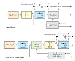
2. Linear and switch-mode power supplies.
Chapter 7, Power Supplies, includes linear and switch-mode types, as shown in Fig. 2. The transformer in a switch-mode supply performs the same function as in a linear supply but now operates with a high-frequency square wave instead of a low-frequency sine wave. The smaller transformer allows a physically smaller power supply.
The author advocates that you should not design a power supply yourself if you can buy it off-the-shelf. However, there are times when there is not enough space or you need special design requirements. Advantages of using a standard off-the-shelf unit are that it saves a considerable amount of design and testing time, the resources for which may not be available in a small company with short timescales.
A major consideration is efficiency due to power loss sources:
- Transformer: core losses, determined by the operating level and core material, and copper losses, determined by I2R, where R is the winding resistance.
- Rectifiers: diode forward voltage drop, VF, multiplied by operating current.
- Linear regulator: the voltage dropped across the series-pass element multiplied by the operating current; greatest at high input voltages.
- Switch-mode regulator: power dissipated in the switching element due to saturation voltage, plus switching losses in this and in snubber and suppressor components, proportional to switching frequency.
With the increasing availability of very compact microprocessors and high-quality power devices, there has been the development of solid-state protection circuits ranging from simple fuses to advanced configurable protection devices. These solid-state devices can be considered under the generic term SSPC solid-state protection circuit.
Chapter 8, Electromagnetic Compatibility, is a design consideration because all electrical and electronic devices generate electromagnetic interference (EMI) and are also susceptible to it. The designer must reduce this generation and susceptibility to acceptable levels. With the increasing penetration of solid-state electronics into all areas of activity, acceptable levels of interference have become progressively tighter as physical separation between devices has reduced and reliance on their operation has increased.
The author notes that a common response of circuit designers when they discover EMC problems late in the day is to specify some extra shielding and filtering in the hope that this will provide a cure. However, this brute-force approach may not be necessary if you put in some extra thought at the early circuit-design stage. Shielding and filtering costs money, circuit design does not.
Most design for EMC is just good circuit-design practice anyway. The most fundamental point to consider is the circuit’s grounding regime: authorities on EMC agree that the majority of post-design interference problems can be traced to poor grounding. Printed circuit layout also has a significant impact. Short, direct tracks running close to their ground returns make very inefficient aerials and are therefore good for controlling both emissions and susceptibility.
Chapter 9, General Product Design, describes how electronic equipment must be designed for safe and reliable operation.
There are various safety requirements for different product sectors. In some cases, compliance with these standards is mandatory. In the European Community, the Low Voltage Directive (73/23/EEC) applies to all electrical equipment with a voltage rating between 50- and 1000-V ac or 75 and 1500-V dc.
Most safety specifications require inaccessibility to the equipment. Any openings in the equipment case must be small enough that the standard test finger cannot contact a live part.
The reliability of electronic equipment is an important consideration. For most of the life of a piece of electronic equipment, its failure rate is constant. In the early stages of operation it could be high and decrease as weak components fail quickly and are replaced; late in its life components may begin to “wear out” or corrosion may take its toll, and the failure rate may start to rise again. The reciprocal of failure rate during the constant period is known as the mean time between failures (MTBFs).
About the Author

Sam Davis
Sam Davis was the editor-in-chief of Power Electronics Technology magazine and website that is now part of Electronic Design. He has 18 years experience in electronic engineering design and management, six years in public relations and 25 years as a trade press editor. He holds a BSEE from Case-Western Reserve University, and did graduate work at the same school and UCLA. Sam was the editor for PCIM, the predecessor to Power Electronics Technology, from 1984 to 2004. His engineering experience includes circuit and system design for Litton Systems, Bunker-Ramo, Rocketdyne, and Clevite Corporation.. Design tasks included analog circuits, display systems, power supplies, underwater ordnance systems, and test systems. He also served as a program manager for a Litton Systems Navy program.
Sam is the author of Computer Data Displays, a book published by Prentice-Hall in the U.S. and Japan in 1969. He is also a recipient of the Jesse Neal Award for trade press editorial excellence, and has one patent for naval ship construction that simplifies electronic system integration.
You can also check out his Power Electronics blog.
Comment About the Article
To join the conversation, and become an exclusive member of Electronic Design, create an account today!

Leaders relevant to this article: