Five PC-Based Production Measurement Traps And How to Avoid Them
When you move a data acquisition system from the controlled environment of the laboratory to the shop floor, many factors may combine to destroy your measurement accuracy at best-or your equipment at worst. An understanding of these factors is crucial to measurement success.
Through our applications support program, we have identified five recurring roadblocks to successful measurements in production situations. They are presented here in the order of most to least common, together with some real-life examples. By the time we’re through, hopefully you will have a greater understanding of the rigors of production measurements and be better equipped to choose instruments that are appropriate for any given application.
Crosstalk
By far, the most common question we field involves a phenomenon that superimposes the content of one data acquisition channel on another. This condition, known as crosstalk, can lead to subtle measurement errors that may take some time to detect. In its most gross form, however, a nearly exact duplicate of one channel appears on an adjacent channel to which nothing is connected.
The PC-based instrumentation revolution spawned active use of the multiplexer. It is driven by the promise of a low cost per channel in the range of $30 to $40 each. But along the way, many products have dropped a hallmark of traditional instrumentation: an amplifier per channel.
Products that lack this feature connect the multiplexer’s inputs directly to the system-under-test. As in many of the other measurement situations that follow, the multiplexer is not an ideal device. Its inputs have capacitance that can, and do, store a charge in a magnitude directly proportional to sample rate and the impedance of the signal source. It is this characteristic that causes crosstalk.
Consider an application where a multiplexer’s inputs are connected directly to the output of an amplifier. In this situation, the impedance the multiplexer sees is stable and low, about 10 W. Crosstalk is greatly minimized or eliminated altogether since the impedance of the source is low enough to bleed the charge on the multiplexer’s input capacitance before the analog-to-digital converter (ADC) reports a value.
Even under this nearly ideal impedance situation, a high sample rate can boost crosstalk by minimizing the dwell time on the multiplexer’s channels. In effect, the capacitance has less time to bleed its charge before analog-to-digital conversion takes place, resulting in crosstalk where none existed before.
As source impedance and sample rate increase, the probability for crosstalk increases as well. To avoid this trap, keep these points in mind:
-
Minimize the source impedance of your signal source. As a rule of thumb, try to keep it below 100 W; although at very high sample rates, even this value may be too high.
-
If you can’t control source impedance to minimal levels, consider placing an amplifier between your signal source and the PC-based instrument. Better yet, choose an instrument with a built-in amplifier on each channel.
-
Minimize the instrument’s sample rate whenever possible. Consider an instrument that allows you to control the burst sample rate of the product for added flexibility.
Common-Mode Voltage
Although crosstalk leads the pack in sheer volume of application inquiries, common-mode voltage (CMV) leads in its capability to confuse. More traditional measurement methods, like battery-powered, hand-held DVMs, are almost impervious to CMV problems.
Naturally, customers think they can simply extend this success to PC-based measurement approaches. In many cases, they do so with poor or even disastrous results.
The problems they encounter can be tied to two specifications on the manufacturer’s data sheet: full-scale range and maximum input voltage without damage. The former tells you how much voltage connected right across the instrument’s inputs, the so-called normal-mode voltage (NMV), you can successfully measure. As its name implies, the latter indicates how much NMV the instrument will tolerate before it’s damaged.
CMV, the voltage that appears simultaneously and in phase on each of the instrument’s inputs with respect to power ground, will combine with the NMV to test the limits of your instrument. Most data acquisition products for the PC permit measurements when a combination of CMV and NMV exists only as long as their sum is equal to, or less than, the instrument’s full-scale range.
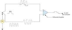
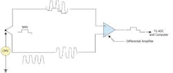
The measurement can be made under these conditions only if the input of the data acquisition product is configured for differential operation, as shown in Figure 1. With the basic rule for differential measurements established, it’s now appropriate to detail the three possible results of such measurements in order of best to worst:
-
(CMV + NMV) £ Full scale range: This is a good measurement, subject to the common-mode rejection (CMR) specification of the instrument.
-
Full scale range £ (CMV + NMV) £ Maximum input voltage without damage: Your measurement is latched at plus or minus full scale. You have no usable results, but no damage either.
-
(CMV + NMV) £ Maximum input voltage without damage: Smell the aroma of ozone in the air? You just fried your data acquisition product and dodged a bullet if your computer still works.
For most data acquisition products, it doesn’t take long to reach the terminal stage of step three. Most will tolerate a maximum input voltage without damage of ±30 VDC or peak AC. In the realm of production measurements, with 120- to 440-VAC motor supplies or even 50-VDC process current supplies, you can exceed this limit very quickly and irrevocably.
Figure 1
How do you apply your comparatively expensive data acquisition instrument to the same measurements you make so effortlessly and safely with your hand-held DVM? You choose a product that provides isolation.
Isolation is what its name implies. As with your battery-powered DVM, there is no electrical connection between the common connection associated with the instrument’s front-end input terminals and the power common connection associated with the back-end of the instrument and the computer.
As such, the instrument’s front-end is free to float at a level defined by the magnitude of the CMV, without damage and with complete measurement accuracy. Here, the maximum CMV that can be tolerated is not dictated by its maximum input voltage specification or even by its full-scale range, but rather by the voltage at which the isolation barrier breaks down.
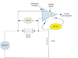
For example, with DATAQ Instruments’ DI-730 data acquisition product, that breakdown occurs at 1,000 VDC or peak AC, well within the expected CMV of most production applications. Figure 2 (below) describes a typical application where isolation allows a measurement in the presence of a high CMV.
Figure 2
Under the heading of buyer beware, isolation can be provided in more than one form: input-to-output, channel-to-channel, and a combination of both. For the vast majority of multichannel production applications, you will need both input-to-output and channel-to-channel isolation. Such an arrangement allows each channel to float with respect to the others.
A CMV on channel one, for example, will not disrupt measurements on the other channels, even if they are referenced to power common or an entirely different CMV. In contrast, systems designed with just input-to-output isolation essentially tie together the commons of all channels. A CMV on one channel floats all at the same voltage with potentially disastrous results if another channel is connected to a ground-referenced signal or a different CMV.
There is only one reason to buy a product that offers only input-to-output isolation. Cost. For example, it is less expensive to build one isolation barrier into an eight-channel product than one for each channel. And the cost savings usually are reflected in lower system price. But in the actual application of such an instrument, you may find that you have simply purchased an expensive fuse.
Before leaving the topic of isolation, I want to establish one point firmly and clearly: You cannot and must not equate a product that offers differential measurement capability with one that offers isolation. These are two entirely different and unrelated features.
Nonetheless, some people still are under the impression that a product with differential measurement capability allows them to apply the instrument in high CMV conditions. As we have seen, differential but nonisolated products tolerate only moderate CMVs without damage and even lower CMVs with good measurement results.
DC CMR
Whenever a measurement is made in the presence of a CMV, accuracy will be adversely affected. The only remaining question is the magnitude of the inaccuracy, and you can determine this by looking up the spec for CMR in your product’s data sheet.
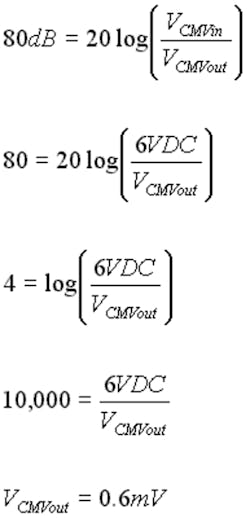
Any instrument that provides a differential input, isolated or not, offers the capability to reject a CMV to a degree determined by its CMR. CMR is most commonly defined as a logarithmic ratio of input-to-output CMV in decibels. The common-mode rejection ratio (CMRR) for most general-purpose, analog-to-digital products for the PC is around 80 dB. How does this figure apply to the measurement? Let’s look at a modest example and work through the math. Assume that you want to measure a 3-VDC normal-mode signal in the presence of a 6-VDC CMV:Measurement Accuracy = 3 VDC ±0.6 mV, or ±0.02%
Not bad for a first try. We started with a CMV that was twice the magnitude of our signal of interest. But our differential amplifier with its 80-dB CMRR spec reduced its effect on the amplifier’s output to fractions of a millivolt with negligible impact on accuracy. Based on this evidence, you might conclude that 80-dB rejection is suitable for all applications.
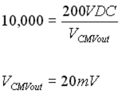
Let’s test this hypothesis in the real-world application shown in Figure 2. Here’s the math, omitting the first three steps that are redundant:Measurement Accuracy = 50 mV ±20 mV, or ±40%
The instrument that worked so well when the spread between the CMV and NMV potentials was narrow (only 2:1 in the first example) literally falls apart when the spread increases exponentially. This is a common situation in many production measurements, like the 4,000:1 spread of the typical current shunt measurement in Figure 2.
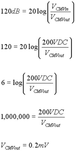
Since you cannot lower the CMV in these situations, the only solution is to apply an instrument with better CMR. Here’s how the math stacks up for the same application using 120-dB CMRR:Measurement Accuracy = 50 mV ±0.2 mV, or ±0.04%
As you can see, knowing how a CMV will affect measurement accuracy is at least as important as knowing that it exists at all. To help you evaluate an instrument you may already have or might purchase, Table 1 provides a guide of the error caused by a CMV as a function of your instrument’s CMRR.
To use it, determine the CMV of the application and look up your instrument’s CMRR spec in its data sheet. Table 1 (see below) provides a range of CMRRs in decibels and their equivalent antilog ratios so you do not have to work with logarithmic math.
Table 1
CMRR (dB)
Antilog Equivalent(10db/20)
20
10
30
32
40
100
50
316
60
1,000
70
3,162
80
10,000
90
31,623
100
100,000
110
316,228
120
1,000,000
General Equation:
Example:
Assume that CMV = 100 V; CMRR = 90 dB
Compare the calculated 3.2-mV error with your signal of interest to determine overall accuracy.
Plug your CMV and the appropriate antilog ratio into the equation shown. The result is the expected measurement error in volts. To determine the instrument’s suitability for the application, compare this figure with the NMV you need to measure.
AC CMR
AC CMVs are at least as prevalent as DC, and even more so when you include unpredictable noise sources such as motor brushes and inductive conducted and radiated EMFs. As such, the assumption of pure DC CMVs may not be supported in actual practice. It’s worthwhile to explore how AC CMVs can adversely affect an amplifier’s CMRR and measurement accuracy.
A differential amplifier’s capability to reject CMVs is tied directly to how well its two inputs are balanced. Falling back to an ideal example, if we connect 1 VDC to one input and 1 VDC to the other, we expect to see 0 V on the amplifier’s output. But we know the amplifier is not, and never will be, ideal.
Stated another way, its CMRR never will be infinite. Small tolerance variations within the amplifier, and even in the system-under-test, will force the amplifier out of balance, however slightly, to yield a finite CMRR value and its attendant inaccuracies. When an AC CMV is applied, a whole set of additive inaccuracies is introduced. The culprit heralds back to the beginning of this article-capacitance.
Under pure DC CMV conditions, any capacitance in the signal source, signal cable, and connectors and within the amplifier itself is inconsequential. As an AC component is introduced, these capacitances form a complex and unpredictable impedance that can force the amplifier out of balance. And this unbalance can and will change as a function of frequency.
To account for this, most manufacturers spec CMRR not under ideal DC conditions, but at 50 or 60 Hz with typically 1,000-W unbalance between the amplifier’s inputs. This is done to provide you with a worst-case estimate for CMRR under the most likely source of AC interference: the frequency of the AC power line. Beyond this, a manufacturer cannot predict what particular frequencies your application may experience.
You could find that an instrument speced at 100-dB CMR yields no better than 80-dB rejection in the presence of higher frequency noise. Yet, the product still operates within spec as defined by the manufacturer.
How do you determine the suitability of an instrument in the presence of noise beyond that of the power line? Unfortunately, there is no easy answer to this question. But bear in mind that a product that successfully addresses such an application does not do so by chance.
Wide-spectrum AC rejection must be built into a product early in its design cycle. Contact the manufacturer and describe your situation. If the manufacturer assures you of the instrument’s suitability, ask for a trial period. In extreme cases, like DC drive systems or other high-speed and high-voltage switching applications, only seeing is believing.
Measurement Range and Input Protection
To this point, we have examined some of the more esoteric, yet highly relevant, issues that you must consider when you apply an instrument to demanding production applications. Other more obvious issues involve the instrument’s measurement range and input protection.
Most production applications will test an instrument’s mettle on both ends of the measurement spectrum-from large source voltages in the range of several hundred volts to small shunt voltages in the range of tens of millivolts. The instrument you choose for these applications should be able to easily select among a variety of measurement ranges. And it should do so on a channel-by-channel basis, since it is very common to measure voltage and current simultaneously.
But the very nature of these highly variable and wide dynamic range measurements carries an implied need for input protection. How many of us are not guilty of ever attempting to measure a few hundred volts on a millivolt range? It happens all the time. Practical input protection should allow any voltage within its maximum-without-damage-range to be connected indefinitely, regardless of the measurement range selected.
Finally, what are the consequences when you really exceed an instrument’s maximum-without-damage range? Is it okay if it’s reduced to a burning cinder? Should you expect more? An instrument designed for the applications we have discussed here should be more forgiving.
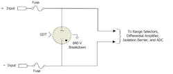
Input protection schemes abound, and none can absolutely protect an instrument from a cataclysmic event. But the damage can be minimized. The technique used most successfully applies a combination of fuses and a device called a gas discharge tube (GDT) in a low-tech, but highly efficient and time-tested, approach to circuit protection that has remained virtually unchanged for decades.
Borrowing again from DATAQ Instruments’ Model DI-730, Figure 3 is a schematic of the first analog input stage, which is typical for each of its eight channels. The theory at work here is simple and straightforward. The GDT is designed to conduct at a specific voltage.
Figure 3
At voltages below this threshold, it’s an open circuit. When an overvoltage condition occurs and the GDT conducts, the fuses take over. At this stage, one or both fuses blow, essentially disconnecting the DI-730’s input from the signal source and, in the process, protecting the bulk of the instrument and the bulk of your investment.
Conclusions
The landscape of data acquisition applications is replete with measurement challenges. But none are more demanding than those encountered in day-to-day voltage and current measurements in the gritty world of industry. Even relatively benign 4-20-mA process current signals, which on the surface seem straightforward, can carry hidden CMVs to confound your best measurement attempts.
Carefully planning the application and studying the data sheets of candidate instruments will help you avoid most of the traps. Even so, the ultimate proof is in the pudding. Express your concerns and questions to instrument suppliers. Factor their input with your experience and eliminate any lingering doubt by insisting on an evaluation-in your facility, connected to your signals, exactly the way you want to measure them.
About the Author
Roger W. Lockhart is vice president of DATAQ Instruments. He graduated from the University of Dayton with an E.E.T. degree and Case Weatherhead School of Management with an M.B.A. DATAQ Instruments, 150 Springside Dr., Suite B220, Akron, OH 44333-2473, (330) 668-1444, e-mail: [email protected].
Return to PC-Based Test Online – Return to EE Home Page
Published by EE-Evaluation Engineering
All contents © 1999 Nelson Publishing Inc.
No reprint, distribution, or reuse in any medium is permitted
without the express written consent of the publisher.
April 1999
