Sensors are the elements at the sharp end of physical measurement systems. Many instruments measure voltage directly, but temperature, pressure, torque, rpm, and most other nonelectrical parameters require indirect measurement via sensors.
Ideally, a sensor should only respond to a single variable and give a stable, repeatable, and linear voltage output. Often, that’s not the case.
Even something as simple as a resistor used to sense current is not perfect. The value of the resistor varies with temperature, the voltage across it, and age. The component leads contribute inductance, a small capacitance shunts the resistance, and depending on the construction of the resistor, the resistive element itself may add inductance. Whether or not these characteristics are important to you depends on the size and speed of your current signal and the accuracy with which you are trying to measure it.
Obtaining good-quality measurements is further complicated by a sensor’s output level and output impedance. Some accelerometers, for example, have built-in preamplifiers because the output from the sensor is very small and the source impedance is high. This combination is a perfect recipe for noise corruption. Amplifying the signal as close as possible to the source minimizes noise pickup and provides a low-output impedance signal to the measuring system.
Whatever is being measured, sensors use a wide range of natural phenomena to represent the parameter faithfully. Three of the most commonly measured variables are temperature, current, and pressure, and sensors developed for them are no exceptions.
Temperature
Several devices are used to sense temperature: thermocouples, a resistance temperature detector (RTD), thermistors, infrared radiators, change-of-state indicators, and bimetallic and liquid-expansion actuators. In terms of unit volume, the bimetallic and liquid-expansion actuators are the most prevalent temperature-sensing devices. These technologies are found in most thermostats, whether used to control a furnace or the water flow in a car’s cooling system, and most thermometers.
By themselves, they produce motion, but contacts have to be added to provide even a basic electrical switching action. In contrast, thermocouples, RTDs, and thermistors either develop a voltage directly or cause a change in voltage in response to a change in temperature.
Thermocouples
When two wires made from dissimilar metals are joined at one end and a temperature difference exists between the joined ends and the open ends, a voltage will appear across the open ends. This voltage is the Seebeck voltage, named after Thomas Seebeck who, in 1821, discovered that a temperature difference caused current to flow in a circuit made of dissimilar metals. Figure 1 shows the relationship between the Seebeck voltage coefficient and the temperature difference for several standard types of thermocouples.
It’s interesting that the properties of the joint between the two materials are not important. Generally, the joint, formed by soldering or welding, will be relatively small. So if the joint were to be inserted in a boiling liquid, for example, the entire joint would be at a constant temperature (an isothermal). The Seebeck voltage is produced by the temperature gradient along each of the thermocouple wires outside of the liquid, not by the joint itself.1
As a result, the excellent correlation between the output voltage and the thermocouple wire composition means that you can expect accurate temperature measurements regardless of the exact nature of the wire joint. If this were not the case, you couldn’t make accurate thermocouples yourself, which you certainly can.
Common K-type thermocouples are cheap but can be accurate to about 0.1°C depending on the temperature range and the linearization that has been applied. Of course, trying to measure the output voltage immediately creates two more thermocouple junctions. The measuring instrument’s terminals probably are made of copper, and a K-type thermocouple uses nickel-chromium and nickel-aluminum silicon wires.
Because of the inconvenience of manually measuring the temperature where the thermocouple wires are connected to the instrument, the so-called cold junction, modern instruments automatically apply cold-junction compensation. Thermocouple instruments also linearize the sensor voltage by applying correction equations with as many as 10 terms.
Nevertheless, thermocouples do present problems. Resolution of 0.1°C for a K-type thermocouple corresponds to 4-µV instrument resolution. This explains why measurement bandwidth usually is low—to reduce noise. The Seebeck effect is consistent and predictable, but small. So, why continue to use thermocouples? Other forms of sensors are easier to work with and give accurate results.
The answer, according to Omega Engineering, is that “thermocouples can be used over a wide range of temperatures [-270 to 2,300°C] and optimized for various atmospheres. They are much more rugged than thermistors, as evidenced by the fact that thermocouples are often welded to a metal part or clamped under a screw.”2
RTDs and Thermistors
Temperature-induced resistance change is the operating principle for RTDs and thermistors. Both types of devices change their resistance in response to a temperature change, RTDs being by far the more precise and expensive of the two.
High-quality RTDs use a small platinum resistance element because this material exhibits a relatively high resistivity with nearly linear temperature dependence. Element resistance is measured accurately and the resulting output linearized to read temperature.
“The details of how these components are fabricated are important,” said Irwin Bluestein, national sales manager at RdF. “Improvements have been made in the attachment of lead wires to thin-film platinum RTDs. Better packaging and encapsulating have resulted in sensors that are more stable and robust.”
Although RTDs are more stable than thermocouples, they only can be used up to about 850°C. The upper temperature limit doesn’t depend on whether film patterns are produced by sputter etching or laser trimming or if wound wire elements are used.
Thermistors are made from manganese, cobalt, copper, and nickel oxides. Generally, they have a large, nonlinear, negative temperature coefficient of a few percent of value/°C. They also share the phenomenon of self-heating with RTDs.
Because neither type of device actually generates a voltage, they must be powered by passing a small current through them. This current produces Joule heating within the resistance.
The amount of heat generated and the resulting measurement errors can be minimized by using the smallest current that will give an output voltage with sufficient resolution. For a typical 100-W platinum RTD, the change in resistance is 0.385 W/°C. This means that to measure a 0.1°C temperature change, you must resolve resistance changes of only 0.0385 W. Temperature rise can be minimized by using the largest size element that is practical.
Pressure Sensors
Some computer-related pointing devices respond to pressure directly. They rely on a type of elastomeric material that changes resistance as it compresses. These materials, however, are not suitable for precise and repeatable pressure measurement.
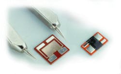
Similarly, piezoelectric materials can be used as pressure-to-voltage sensors, and some accelerometers make use of this effect. Another technique measures the variable capacitance that results from the change in spacing between a fixed plate and a moveable diaphragm. But, most high-quality pressure sensors are based on a strain-gage bridge mounted on a suitable diaphragm that flexes under pressure (Figure 2).
A change in resistance caused by external strain is the principle underlying strain gages. Recently, semiconductor manufacturing techniques have been used to produce very stable gages. The most sensitive sensors use four nominally equal resistors in a Wheatstone-bridge configuration. Even though silicon exhibits a large piezoresistive effect, the output of such a bridge still is only millivolts.
Traditional metal foil-based strain gages can be lower cost than silicon, but generally they won’t provide equivalent accuracy. Each gage resistor must be separately positioned and bonded to the diaphragm.
Silicon pressure sensors can’t be used at temperatures greater than about 125°C because of the excess leakage currents between P-N isolation junctions. To solve this problem, Honeywell manufactures pressure sensors using a silicon-on-insulator (SOI) process. Instead of P-N junctions, the separate strain-gage elements are completely encapsulated in a layer of silicon-dioxide (SiO2) insulator.
Because of their P-N junctions, conventional silicon sensors are limited to the types of gases that can be used in a differential pressure application. Typically, the side of the diaphragm into which the sensing resistors have been diffused should only be exposed to clean air. The thick SiO2 layer formed in the SOI process allows a much wider range of media to be used. Additional benefits, besides a 250°C upper temperature limit, include lower noise, higher operating voltage, reduced voltage and ESD sensitivity, insensitivity to light, and intrinsic radiation hardening.
As another example of silicon sensor technology, Measurement Specialties uses its Microfused process to eliminate P-N junctions. Individual micromachined silicon strain gages are fused to a stainless steel diaphragm using high-temperature glass. Models are available with up to 26,000-psi capability, suitable for use with contaminated water, steam, and mildly corrosive liquids and gases.
Current Sensors
Resistors
There are at least 10 ways to measure current, the most common one being a resistor.3 Some of the imperfections of resistors already have been dealt with in this article; however, the use of Kelvin connections is imperative for high-accuracy measurements.
Precision sense resistors are made from special low-temperature-coefficient alloys such as Manganin and Zeranin®. The thermocouples formed by these materials and copper exhibit a thermal voltage coefficient of 2 µV/°C. To minimize measurement errors, it’s important that the resistor be heated uniformly by the current being sensed.

Current Transformers
For measuring AC or pulse currents, a passive toroidal transformer is effective. The primary consists of one or more wires that pass through the center of the toroid and carry the current to be measured. Because the input impedance is equivalent to the load resistance divided by the square of the turns ratio, current transformers can have a minimal insertion resistance.
Bandwidth is determined by inductance at the low-frequency end, so the core’s permeability and the number of turns are important. Parasitic capacitances and inductance limit the upper frequency response. An accuracy of 0.1% and very wide bandwidths can be achieved in instrumentation-grade devices.
Rogowski Coils
Rogowski coils should not be confused with current transformers. A current transformer has a high-permeability core, such as ferrite, to extend its low-frequency response. A Rogowski coil has an air core. The output from a Rogowski coil must be integrated to be useful. The integrated output is proportional to input current.
The coil has unique capabilities. The two ends can be separated so that the coil can be placed around very large busbars, for example. Because there is no core to saturate, signal-source loading is constant. And, if a large current pulse should overload the Rogowski coil, its integrator may distort the signal, but the output typically will not drop to zero as occurs in a saturated current transformer. Depending on the integrator design, di/dt ranges from 250 A/s to 250 A/ms.
Hall-Effect Sensors
Hall-effect devices produce a small output voltage in response to both DC and AC magnetic-field flux. This means that they can be used in applications where, for example, a DC current component would saturate a current transformer.
Hall-effect devices can be used in an open-loop configuration to measure the total flux corresponding to the current in a wire. In this case, the device linearity is important because the operating point changes with the signal level. A more accurate and much more linear approach uses the amplified output to drive a compensation coil to oppose the flux produced by the original signal. This feedback method attempts to force the total flux to zero, keeping the operating point of the Hall-effect device constant.
These sensors have a relatively low bandwidth of perhaps 25 kHz, but often they are combined with current transformers to extend the range up to approximately 200 kHz for industrial applications. The Tektronix A6312 Current Probe is a good example of a combined Hall-effect/transformer sensor that achieves a bandwidth from DC to 100 MHz.
Magnetoresistive Sensors
Magnetoresistive sensors change resistance in response to a magnetic field much like RTDs do when measuring temperature. A Wheatstone bridge is used to measure the relatively small resistance change. Because these sensors are more sensitive than Hall-effect devices, they do not require magnetic cores, allowing them to be integrated as part of a hybrid current measurement module
References
- www.omega.com/pdf/temperature/Z/pdf/
z019-020.pdf, p. Z-29. - ibid., p. Z-24.
- Wahl, F. P., ed., “Select Current Sensor Performance to Match the Application’s Requirements,” PCIM, 1998, www.pcim.com/articles/1998/art0001/art1.html.
Published by EE-Evaluation Engineering
All contents © 2000 Nelson Publishing Inc.
No reprint, distribution, or reuse in any medium is permitted
without the express written consent of the publisher.
July 2000
About the Author
Comment About the Article
To join the conversation, and become an exclusive member of Electronic Design, create an account today!

Leaders relevant to this article: