With the increased use of electronic products, high-frequency electromagnetic fields have become a common cause of interference. To measure the effects of this phenomenon, a controlled, repeatable environment is required to effectively simulate, measure, and determine the level of product immunity to electromagnetic interference (EMI). For most manufacturers, proof of electromagnetic compatibility (EMC) compliance is a regulatory requirement that must be established before products are sold.
Two types of testing are used to establish EMC compliance:
- Emissions testing is the measure of how much interference the device itself generates. Traditionally, it is conducted in open area test sites (OATS).
- Immunity testing subjects a product to specified EMI fields and monitors its performance.
Immunity Testing Standard
The standard for immunity testing is EN 61000-4-3. The equipment under test (EUT) is subjected to an RF field at 1, 3, or 10 V/m. The level depends on the equipment class and intended operating environment. The frequency span is 80 to 1,000 MHz. The signal is amplitude-modulated at an 80% level with no more than 15% distortion.
In these tests, the enclosed location where the EUT is to be placed must be calibrated and meet field uniformity criteria. To calibrate the site, a 1.5-m × 1.5-m plane is measured at 16 points. The variation between the 16 points must not exceed 6 dB, and at least 1 meter of the EUT cable must be in the radiated field.
Forward power readings generate a calibration file, with an offset to account for the lowest reading from any of the points. This file is used to control the signal source during testing.
The EUT is placed within the uniform area and subjected to the RF field over the appropriate frequency range. The test is repeated for both horizontal and vertical antenna polarizations.
The EUT is actively monitored during the test for any performance degradation or malfunction. The acceptable level of performance degradation should be in line with performance criteria A of EN 61000-4-3. The EUT must maintain the performance level set by the manufacturer.
Testing in a Screened Room
Immunity testing must be conducted in an enclosed area because it is illegal to radiate radio waves at frequencies for which you do not have a license. Also, the RF field that must be generated is likely to interfere with sensitive equipment nearby.
The two basic types of immunity-testing enclosures are a screened room and a test cell. Unfortunately, testing in an unlined screened room gives rise to many problems. The reflections and resonances make control and repeatability extremely difficult if not impossible.
The solution is to line the room with radio-wave absorbent, anechoic material. This comes in two generic types:
- Ferrite tiles, which usually are somewhat costly but save space.
- Carbon-loaded foam, which is less expensive but takes up more space and requires a larger screen room.
Both materials absorb energy from the waves. The tile dissipates the magnetic field energy and the foam the electric field. A semi-anechoic chamber has RF-absorbent materials on the walls and ceiling, while an anechoic chamber has the absorbent materials on the walls, ceiling, and floor.
The GTEM Cell
The gigahertz transverse electromagnetic (GTEM) cell offers an economical alternative to the screened room for immunity testing. Also, it represents a marked improvement over the original Crawford TEM cell, which is limited in frequency range.
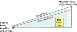
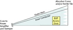
A GTEM cell expands pyramidally from a round coaxial feeding point to a rectangular waveguide. It has a flat inner conductor (septum), which is offset from the middle of the cell to enlarge the usable test volume. The cross section is designed to maintain an impedance of 50 W.
At the large end of the cell, the waveguide is terminated by a combination of discrete resistors and RF absorbers. The enclosure of the GTEM cell, effectively the outer conductor of the waveguide, consists of special metal walls that have suitable attenuation for electromagnetic fields as illustrated in Figure 1.
Figure 1. Principle of the GTEM
The termination resistors are made up of large-surface PCBs. Each board has several individual resistors to achieve the 50-W impedance and provide sufficient power-handling capability. Because of the geometrical expansion of the cell, the termination resistance is effective in a limited frequency range. Beyond these frequencies, RF absorbers provide the low reflection termination.
When RF signals are fed into a waveguide, waves propagate around the inner conductor. In this scenario, far-field conditions prevail where the electromagnetic field exists as a plane wave. The electric and magnetic field vectors are perpendicular to each other, and both are perpendicular to the direction of the propagation. This produces a uniform field within the GTEM similar to the field in the screened room/anechoic chamber and which complies fully with EN 61000-4-3. Additionally, the intensity of the field in volts per meter is directly proportional to the applied voltage and the distance between the inner conductor and ground.
Testing in a GTEM Cell
In immunity testing, the GTEM has a wide range of usable frequencies from DC to 18 GHz, and the generated fields are homogeneous. It has good repeatability and accuracy. The installation and servicing costs are low. No interfering radiation is released to the environment, and measurement results are not affected by environmental factors. Finally, calibration and measurement times are short. Figure 2 shows a typical GTEM test-system configuration.
A GTEM cell also exhibits the reproducibility required by EN 61000-4-3 for a given test volume. The uniform field typically exceeds one-third of the separation between the outer and inner conductors. Because a GTEM cell test system doesn’t incorporate an antenna, polarization is achieved by rotating the EUT within the cell. This makes the GTEM suitable for full-compliance immunity testing of small electronic equipment.
The Future of the GTEM Cell
The GTEM cell supplies a universal facility for testing small and mid-sized equipment and a favorable cost-performance ratio. GTEM cells can be certified for a wide range of test requirements.
For some of the smallest products, a more economical GTEM cell such as the GTEMLite by Schaffner EMC is available. This offers a no-frills environment for emissions testing to 2 GHz and immunity testing to 5 GHz.
About the Author
Greg Senko manages the Schaffner EMC Test Equipment Division in North America. He holds a B.S.E.E. from Northeastern University and has worked in the EMC industry for 18 years. Schaffner EMC, 52 Mayfield Ave., Edison, NJ 08837, 800-367-5566, e-mail: [email protected].
Return to EE Home Page
Published by EE-Evaluation Engineering
All contents © 2001 Nelson Publishing Inc.
No reprint, distribution, or reuse in any medium is permitted
without the express written consent of the publisher.
February 2001

