Network designers frequently are called upon to maximize the performance of their networks, yet they often do not have a clear, consistent methodology or the proper equipment for measuring this performance. The situation quickly becomes exacerbated, not to mention expensive, when network problems crop up after deployment.
Ideally, you should be able to identify and isolate potential problems in the design and evaluation stage of network development. This predeployment approach to network optimization would go a long way toward eliminating rude surprises and angry phone calls at the help desk.
However, the process of devising a set of parametric tests and creating the equipment for measuring performance often is beyond the capabilities and scope of duties for the typical network designer. Fortunately, a number of companies specialize in the development of network performance measurement equipment.
Additionally, many industry-recognized methodologies can be used to provide a set of fair and consistent tests across a wide variety of network vendors’ equipment. The combination of equipment and methodologies provides a complete answer for anyone who needs fair and accurate network performance measurement.
Test Objectives
Stated simply, the objective of any test is to justify confidence in the network design. To qualify the validity of a set of tests, engineers must ensure that they test against the anticipated failure modes. This requires them to logically analyze the network design for potential errors and come up with a set of specific test methodologies.
Since there are nearly an infinite number of network topologies, it is impractical to devise a set of industry-standard tests to address each topology. Instead, the Internet Engineering Task Force (IETF) has produced a set of requests for comment (RFCs) that addresses a wide range of testing issues down to the resolution of a network test element. At this level, it is anticipated that all network elements, such as switches and routers, hold similar objectives and can be tested with a common methodology.
In general, network test methodologies consist of the following categories:
- Throughput—The device under test (DUT) must faithfully deliver all frames of information to the proper destination.
- Latency—The DUT must deliver frames of information within a reasonable period of time.
- Jitter—The variation in latency over time, also known as latency jitter, must be bound to predictable limits.
- Integrity—The DUT must deliver its frames without corrupting any of the contents.
- Order—The DUT may have restrictions on whether or not frames of information can be re-ordered as they traverse the system.
- Priority—The DUT may have to prioritize different types of frames so that only lower priority frames are dropped during times of peak congestion.
This list is not exhaustive. It simply addresses test objectives for some of the more common network errors.
To test against these categories, use test equipment that can operate beyond the limits of the DUT. This eliminates doubt about whether any anomalies were due to the DUT or the test equipment itself.
It rapidly becomes clear that the test equipment must consist of specially designed hardware created for the specific purpose of testing network equipment. In other words, a network interface card (NIC) in a PC simply won’t have the capacity to sufficiently test a DUT with the desired margin.
To address the test categories, the test equipment must be capable of the following:
- Generate frames at speeds at or above the theoretical maximum for the media over which the test is being conducted, count incoming frames from the DUT, and ensure that all transmitted frames have been received.
- Insert an accurate time-stamp into the data portion of transmitted frames, receive and analyze time-stamp information embedded in received frames, and calculate the corresponding latency.
- Compile latency statistics from item 2 so that latency variation over time can be illustrated.
- Within transmitted frames, encapsulate the field(s) inside an envelope with proper error-checking codes. Typically, a cyclic redundancy code (CRC) can be used for this purpose. On received frames, check the error code to ensure that the encapsulated field is uncorrupted.
- Insert a counter into transmitted frames and check the value of counters in received frames. Inconsistencies in the received count value generally are indicative of problems with frame ordering. Maintain the capability to distinguish between missing frames and frame order errors.
- Transmit various types of frames with different priorities. For example, this may be accomplished by altering type-of-service (TOS) bits in an Internet protocol (IP) header. Intentionally overwhelm the DUT with such traffic, forcing it to engineer its traffic according to frame priorities. Separate incoming frames from the DUT based on priority. Count frames associated with each priority to determine whether or not the DUT correctly engineered the traffic.
These objectives place some challenging requirements on the design of the associated test equipment. Consider that each frame must be created and analyzed in real time. Also consider that today’s optical networks are running at speeds up to and beyond 10 Gb/s. Even at 10-Mb local area network (LAN) speeds, you would need to create and analyze frames at speeds beyond 14,000 frames/s.
The trend among test-equipment vendors is to make use of field programmable gate arrays (FPGA) that can be programmed on the fly to generate and analyze traffic at the required speeds. Since these FPGAs are field programmable, they can be reprogrammed onsite for custom applications. Finally, software for such systems generally allows network designers to execute industry-standard methodologies as well as customize the operation to address any special testing needs as required by an implementation.
Examples
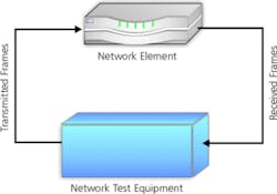
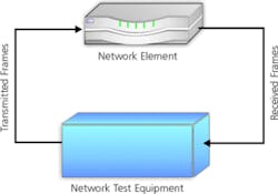
Figure 1 (see below) depicts a typical test scenario where the throughput of a Layer 3 DUT is determined. This figure itself is very simple because the test equipment plays both ends of the field, such as submitting frames on one side and collecting frames on the other side.
Figure 1. A simple test setup for qualifying a single network element.
A deeper examination, however, reveals that the test scenario is not as simple as Figure 1 would lead you to believe. The scenario becomes complicated because the test equipment first must blaze a trail through the DUT. This effort can range from simple to complex as you migrate up through the OSI stack.
When testing traffic above Layer 3, the process is moderately easy. We assume that all ports are on different virtual LANs (VLANs). In these circumstances, the following process is executed:
- Each port identifies itself to the DUT using the Address Resolution Protocol (ARP).
- In response to the ARP, each port verifies that it receives an ARP response from the DUT.
- Each port creates a set of frames, each of which is destined to another specific port on the tester.
- Created frames are loaded into each port’s transmit buffer and prepared for transmission. An interframe gap (IFG) is calculated for all frames, based on 100% bandwidth. To begin this process, we assume that IFG1 is the minimum frame gap that will achieve the 100% theoretical bandwidth. Set the iteration counter n to 1.
- All frames on all ports are transmitted to completion.
- Wait for all residual frames to traverse through the DUT.
- Count all received frames on all received ports.
- Do one of the following:
a. If all transmitted frames were received and n = 1, the test is complete, and IFG1 can be used to calculate the throughput.
b. If all transmitted frames were received and n ¹ 1, then reduce the gap time as follows:
IFGn+1 = ½ (IFGn + IFGk)
where: IFGk = the next lowest unsuccessful gap time.
c. If all transmitted frames were not received, then increase the gap time as follows:
IFGn+1 = ½ (IFGn + IFGk) or 2×IFG, whichever is greater
where: IFGk = the next higher successful gap time. - Evaluate |IFGn – IFGn-1| / IFGn-1 × 100. If less than 1%, then terminate the test with the final result of IFGn-1 being used to calculate the final throughput.
- Go back to Step 5.
This algorithm is a simple implementation of the throughput test as described in IETF RFC 2544. Though this may seem a bit complex at first, keep in mind that it is a simple binary search algorithm that quickly finds the final throughput. Essentially, the test equipment continuously adjusts the bandwidth until a frame rate is found where no frames are lost.
Figure 2 adds an element of complexity. In this case, several routers are connected together, and the test equipment conducts a similar binary throughput test with a couple twists. First of all, the test equipment must establish a pathway through the routers to run its traffic. The test equipment simply cannot run ARP packets to the routers and expect them to automatically know what to do with the test traffic.
Secondly, the routers run the ReSource ReserVation Protocol (RSVP) signaling protocol to allocate tunnels through which frames may pass. Also, the routers are running the Open Shortest Path First (OSPF) protocol to organize themselves into a group. Then, the test equipment must perform the following steps to obtain throughput information:
- Participate in the OSPF protocol to glean route information from the routers.
- Using the RSVP protocol and drawing on information obtained in Step 1, create one or more tunnels through which test data can flow.
- Create frames of data and perform the throughput test as described in the previous example.
- Maintain the tunnels and the OSPF sessions for the duration of the test.
As it turns out, this sort of capability cannot be accomplished through FPGAs alone. At this level of sophistication, it also requires a great deal of CPU power to achieve these objectives. Yet, the FPGAs are necessary to perform Step 3. As a result, both the CPUs and the FPGAs must work together seamlessly to accomplish network test objectives.
Summary
The issue of network test is a highly complicated and evolving story, and its importance in network design and deployment cannot be overestimated. Network designers are extremely motivated to understand the objectives of network testing. And as their designs grow more complex, they make more and more demands on their testing solutions.
Fortunately, the broad variety of today’s network test solutions is sufficiently robust to meet the challenges these engineers pose. With programmable hardware, a good helping of CPU power, and sophisticated software, network test equipment has become an invaluable tool for any network designer.
About the Authors
Dan Schaefer is a system engineering manager at Ixia. He has a B.S.E.E. from the University of Missouri, Columbia and has been working in the datacom industry for more than 12 years. Ixia, 26601 W. Agoura Rd., Calabasas, CA 91305, 818-871-1800.
Return to EE Home Page
Published by EE-Evaluation Engineering
All contents © 2001 Nelson Publishing Inc.
No reprint, distribution, or reuse in any medium is permitted
without the express written consent of the publisher.
August 2001

