The asymmetrical digital subscriber line (ADSL) is telephony’s solution for overcoming the local-loop bottleneck and providing fast Internet service to bandwidth-hungry consumers. Many telco carriers today deploy systems compliant to the ANSI T1.413 specified discrete multitone (DMT) modulation scheme, which also has been endorsed by the International Telecommunication Union (ITU) as G.992.1 (G.DMT). But, as carriers race to deploy the technology, they also must find viable solutions to test ADSL.
Why Test?
Mass ADSL deployment has been hindered mainly by unpredictable local-loop conditions. ADSL performance has proven vulnerable to many common elements found in the local loop: load coils, bridge taps, crosstalk from other services, and the cable length and gauge between the central office (CO) and the customer premise. How can a provider know if ADSL service can be supported in an area before investing a large stake in installation?
Traditional test methods are inadequate to truly assess the local plant, and consequently, loop prequalification has been ineffective. Previously, the only method to qualify a circuit was a plug-and-pray approach connecting an actual digital subscriber line access multiplexer (DSLAM) at the CO to an actual ADSL transmission unit-remote (ATU-R) modem at the customer premises. Test equipment now is available that emulates the ATU-R modem and presents crucial bit-rate and noise-margin data.
ATU-R emulation is limited because it requires a working DSLAM. ATU-R emulation is an ideal method for installing ADSL circuits but does not address the thousands of circuits existing today whose local CO is not yet equipped with DSLAMs. Further, setting up a DSLAM for test purposes is not easy, requiring many man-hours for proper wiring, workstation setup, and operation.
The foreboding question looms for service providers: Will deployment be possible in those untested areas? In the war for new broadband subscribers, true ADSL circuit prequalification is paramount for telcos combating the formidable cable-modem industry.
True Loop Qualification: ATU-C Emulation
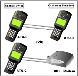
Fortunately, the solution to the prequalification dilemma has arrived. ADSL transmission unit-central office (ATU-C) modem emulation is the key to predicting in-service performance for the thousands of untested circuits. It enables providers to qualify and predict ADSL performance for each circuit long before a DSLAM is installed and running in the CO (Figure 1, see below).
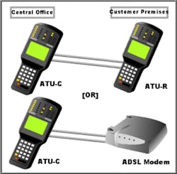
Figure 1. ATU-C Emulation
The key is to use a tester such as the SunSet xDSL with the capability to measure all the necessary parameters, such as downstream rate, upstream rate, and the desired noise margin. These parameters are identical to the settings found in an actual DSLAM.
Fixed vs. Rate Adaptive
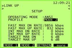
DMT modems have two primary modes of operation, which are settable only at the ATU-C modem in the DSLAM: fixed (mode 1) and rate-adaptive at start-up (mode 2). The major difference between modes 1 and 2 is the realized noise margin.
The primary purpose of mode 1 is to deliver the user-specified bit rate. For this reason, the noise margin will have a wide range, depending on line attenuation and noise conditions. In contrast, mode 2 tries to deliver the maximum rate possible while achieving the target noise margin.
As a result, the realized noise margin of mode 2 always will be less than or equal to the target noise margin. The modems will have less noise margin to compensate for increased line noise before failure. Consequently, providers should use a high target noise margin when using mode 2 for commercial service.
Mode 1: Fixed Rate
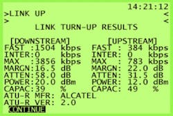
Mode 1 is useful for the provider who has determined fixed rates for commercial service. For example, a provider is offering a service rate of 1,504 kb/s downstream and 384 kb/s upstream. Using the ATU-C test set, you simply enter in this data and train the modems.
Mode 2: Rate-Adaptive
- • Meet the minimum bit-rate threshold.
- • Deliver the highest bit rate possible while maintaining the target noise-margin threshold.
Selecting the Path: Fast vs. Interleaved
Two latency paths, fast and interleaved, may be used. For either path, DMT systems use a forward error correction (FEC) scheme, which ensures higher data integrity. To ensure maximum noise immunity, an interleaver may be used to supplement FEC.
Essentially, an interleaver is a buffer used to introduce a delay, allowing for additional error-correction techniques to handle noise. Interleaving will slow the data flow and may not be optimal for real-time signals such as video transmission. Interleaving is ideal for Internet traffic and used in ITU G.992.2-compliant G.lite systems. With the SunSet xDSL ATU-C module, both the fast path and interleaved path may be tested with simple menu choices to forecast performance for various applications.
Selecting the Noise Margin: Critical
Proper noise-margin settings are critical for running meaningful tests. The target noise-margin parameter represents the signal-to-noise ratio that modems must achieve at turn-up. A 6-dB target noise-margin setting is a common industry practice in these early stages of deployment.
Upon link-up, the modems will maintain synchronization (also known as showtime), as long as the realized noise margin is above the minimum noise margin threshold, which typically is set at 0 dB. For the Alcatel ADSL system, a 0-dB noise margin is the minimum level that ensures the G.DMT bit error rate (BER) performance requirement of 10-7.
Testing various target noise-margin settings is invaluable. Disturber effects still are an unknown factor in ADSL deployment. For instance, impulse noise has been known to cause a sudden 10-dB drop in the noise margin for longer circuits, often resulting in brief modem failure. For this reason, a higher target noise-margin setting may prove wise in the long run, at the cost of disqualifying a few marginal circuits.
The payback is fewer angry customers. For problem circuits where synchronization cannot be achieved, a lower target noise-margin setting should be used for troubleshooting. For instance, a 3-dB target noise margin may produce a synchronization providing valuable diagnostic information.
Showtime
Carrier Mask: Spectrum Management Tool
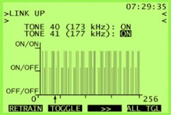
A powerful feature of ATU-C emulation is the carrier mask, which enables you to manually control each of the 256 carriers. Masking carriers aids in combating crosstalk interference, the insidious phenomena that can potentially cause major havoc for service providers. Many DSLs and other services such as integrated services digital network (ISDN) and 1.544-Mb/s digital network (T1) share the same frequency region within the DMT spectrum.
While DMT systems are expected to compensate for crosstalk, more traditional line codes such as T1 bipolar 8 zero substitution/alternate mark inversion (B8ZS/AMI) or 2 binary/1 quaternary (2B1Q) may be adversely affected. Carrier masking enables the provider to experiment and determine optimum settings. For example, if there are known T1 lines in the same binder groups or ones adjacent to various ADSL DMT circuits, the operator can mask the tones surrounding the T1 Nyquist frequency of 772 kHz. This action may reduce the harmful crosstalk effects on the T1 services.
Carrier masking also can help conserve power for DMT systems. In regions where AM radio stations are present, the ineffective tones sharing the same frequency band can be shut off. The troubleshooting results obtained from carrier mask testing will prove invaluable to the provisioning center, which can adjust the customer’s profile to avoid future circuit problems.
About the Author
Steve Kim is a product marketing manager responsible for the xDSL line of equipment and software at Sunrise Telecom. He holds an engineering degree from UC Berkeley and has been with Sunrise since 1996. Sunrise Telecom, 22 Great Oaks Blvd., San Jose, CA 95119, 408-363-8000, e-mail: [email protected]
DMT
DMT technology uses a frequency spectrum up to 1,100 kHz to simultaneously deliver high bandwidth data and voice over a single phone line. A total of 256 tones, each with 4.3-kHz bandwidth, are transmitted in parallel to deliver rates up to 6.144 Mb/s downstream, 640 kb/s upstream.
Tones with high bit allocation have the higher signal-to-noise ratio. For example, if there is a significant drop-off in the bit distribution around 772 kHz, it is highly possible that an interfering T1 source is affecting the DSL performance.
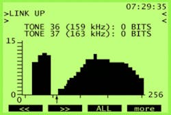
The bits-per-tone feature measures the bits-per-tone distribution used by the modem to transmit the provisioned rate. It displays the number of bits assigned per tone in either a graphic or tabular format. During modem initialization, a signal-to-noise measurement is made for each tone, then bit distribution is optimized to meet the desired bit rate. Each tone can support a theoretical maximum of 15 bits.
During operation, the bit distribution may be adjusted to optimize bandwidth. The modems constantly monitor the signal-to-noise ratio for each tone. If a tone degrades in quality, a bit-swap command can be sent to adjust the number of bits assigned to that particular tone. These bits may be added to a different tone or taken out completely.
The carrier tones at the left of the screen in Figure 5 (low-frequency) represent the upstream signal. The highest frequency for the upstream should be 140 kHz. The group at the right (at the higher frequencies) represents the downstream signal. There can be anywhere from a 20- to 40-kHz buffer between the upstream and downstream frequencies. The arrow is pointing at this buffer space. Note that zero bits are assigned to tones 36 and 37 (frequencies 159 and 163 kHz).
Return to EE Home Page
Published by EE-Evaluation Engineering
All contents © 2001 Nelson Publishing Inc.
No reprint, distribution, or reuse in any medium is permitted
without the express written consent of the publisher.
October 2001
