New Switching and Interfacing Enhance Transceiver Testing
BridgeWave Communications provides wireless links to complement and extend existing wired networks. These solutions enable operators of fiber, hybrid fiber coax, and digital subscriber line networks to cost-effectively extend the networks to subscribers located beyond the reach of their wired infrastructures.
This technology requires a mix of broadband wireless millimeter wave transceivers operating at various frequencies from 10 to 40 GHz. Each transceiver product comprises several modules that must be tested individually and then finally as a complete system. Since these transceivers also are outdoor units, they must meet rigorous outdoor environmental requirements.
Test Challenges
The cost of microwave test equipment can be very high, in excess of $250k. As a result, it was necessary to develop cost-effective test stations for high-mix, low-volume production to cover the 10- to 40-GHz frequency range. The goal was to develop a single station for production testing of modules and final-system and environmental stress testing using temperature plates and ovens.
Although there are many aspects associated with developing a cost-effective test station, the following challenges are linked with the interfacing and signal-switching aspects:
- A modular design to support multiple tests and six devices under test (DUT).
- Integration of commercially available test equipment.
- Highly accurate measurements to 40 GHz.
- Reduction of the complexity and quantity of the interface test adapters (ITAs).
- Reduction of switchover time between various ITAs.
- Reduction of the need for complex microwave switching customization.
-
Minimization of recalibration between various ITAs.
Approach
In the past, the interface to microwave DUTs always was hardwired to the test station through an ITA. Microwave blind-mate connectors were not available, and switching-system manufacturers did not provide off-the-shelf modular and programmable switch matrices, especially at 40 GHz. This resulted in either multiple test stations with redundant instrumentation or overly complex ITAs.
BridgeWave evaluated current blind-mate interfacing systems and modular switching systems to achieve a cost-effective interfacing solution. This eliminated the need for costly microwave components in custom test adapters per DUT.
The main technical challenge was to maintain performance to 40 GHz. The test system needed to provide flat transmission performance to and from the DUTs and sufficient power to the DUTs with at least 20-dB return loss at the test reference plane.
Selecting the Modular Switch Platform
Traditionally, GPIB interface boxes control microwave components. This approach, however, lacks the scalability and modularity up to 40 GHz required for a common test station. We looked at various PC bus card alternatives, such as ISA and PCI. All the PC bus solutions required considerable custom engineering to control the microwave components.
A recent extension of the PC bus is the PXI platform. We only found microwave switch solutions to 18 GHz on PXI, and the form factor of the platform required us to use multiple chassis, making the overall cost too high.
The VXIbus was the last platform we considered because of the perceived high cost. Products were easily available on VXI with switches in all form factors, such as transfer switches, terminated and nonterminated multithrow switches, and SPDTs up to 40 GHz.
Additionally, digital I/Os, DACs, precision DMMs, high-channel count general-purpose switches, and arbitrary waveform generators for I and Q waveforms were readily available. The complete general-purpose instrumentation suite and switch solution could be housed in one chassis, and surprisingly, the overall cost was lower than the other solutions we considered.
Selecting the Modular Interface
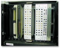
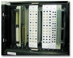
Instead of designing a custom blind-mate scheme, we worked closely with manufacturers of standard blind-mate connectors that provided excellent performance to 40 GHz. A blind-mate connector accommodates threadless connector mating when engaging an array of connectors on one module to another array within seconds.
An interface connector assembly (ICA) that could be mounted directly onto the VXI mainframe was selected. Pull-through interface blocks were chosen to provide a direct mount to the VXI cards and pins for critical alignment to the ITAs as well as to reduce the length of cabling from the switch and instruments. This approach offered the best signal integrity plus easy maintenance and quick replacement of instruments and switches in case of failure.
ITA Design
Using blind-mate interfaces and modular switching allowed the design of the ITAs to be simple point-to-point wiring. All high-frequency cables mount directly to the internal connectors or components to minimize the number of interfaces. DC power and control are routed to the front-panel interface.
Due to temperature testing requirements, the ITAs must support multiple DUTs at one time. The wide bandwidth capabilities of the test equipment, switches, and interfaces enable one ITA to test transceivers at various frequencies.
Attaching an ITA to the test system is facilitated by using a single handle to align and connect the blind-mate connectors.
Performance
Return loss at the test interface for all high-frequency ports was specified at 20 dB. To achieve this level of performance requires all components and cables in the transmission path to have better than 20-dB return loss and flat transmission.
The performance of the VXI high-frequency switch card and blind-mate connectors met these requirements. Figure 2 shows the ITA performance of the high-frequency path that routes the signal output of the DUT to the spectrum analyzer through multiple connectors and switches. As shown, the return loss at the DUT reference plane is greater than 20 dB, and the transmission is flat, delivering excellent performance to 40 GHz.
Due to the high performance of the connectors, recalibration rarely is needed.
Conclusion
Removing the microwave switches from multiport ITAs provides much simpler design and fabrication of ITAs. Using coaxial blind-mate connectors allows easy mounting of various ITAs to the same test system. This, in turn, enables the test system to be easily changed from module testing to final testing, reducing the amount of capital equipment required.
Another benefit of the integrated VXI approach is derived from the use of vendor-supplied software. This provides a consistent user interface and reduces software development time considerably. Also, the software supports off-the-shelf switch and VXI card replacement.
About the Author
Michael Pantalon, a senior test engineer at BridgeWave Communications, has 20 years of experience designing and developing microwave and RF test systems. He holds a B.S. in electronic engineering from California Polytechnic San Luis Obispo. BridgeWave Communications, 3350 Thomas Rd., Santa Clara, CA 95054, 408-567-6900, e-mail: [email protected]
Return to EE Home Page
Published by EE-Evaluation Engineering
All contents © 2001 Nelson Publishing Inc.
No reprint, distribution, or reuse in any medium is permitted
without the express written consent of the publisher.
October 2001

