The rapid evolution of technology has lead to miniaturization of products. These changes have dictated a shift in the design of shock machines used to test such products.
Hardware Issues
The changes in product response dynamics and test specifications brought on by miniaturization now require higher performance from shock machines. Product design dictates the relationship between the dynamics of response and the specifications for the test shock.
Reduced to its simplest elements, when a component is caused to resonate at its basic modal frequency by a shock, the highest potential for damage will occur when the driving shock’s frequency matches that of the resonant component. In other words, if we assume an imaginary product with a major component resonance at or near 500 Hz, a shock pulse with a duration of 0.002 s would force it into a potentially destructive response.
As test items become miniaturized, the decrease in component masses results in much higher resonant frequencies. For example, a new 1-in. size computer hard-disk microdrive may have a stack modal frequency perhaps 10 times higher than its 3.5-in. predecessor.
To accomplish the same type of shock test on this new product, a shock machine capable of high-amplitude shocks at 1/10th the duration of the older machine would be required. Where previously a 2-ms shock duration was acceptable, it may now require a duration of 0.2 ms. To obtain the velocity changes (ΔV) required, the pulse amplitude also must be higher.
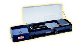
Such short-duration, high-amplitude shocks are the domain of the mechanical shock machine. While electrodynamic shock machines are programmable over wide ranges of duration, they ultimately become limited by the response bandwidth of their control and actuation components.A new type of shock machine that produces high-amplitude, short-duration shocks is shown in Figure 1. The small, horizontal-motion, storedenergy machine designed for testing miniaturized products features a 10″ × 10″ table and provides shocks in the X-Y plane.
Energy is accumulated in driving springs compressed by an air cylinder. Pulse amplitude and duration are user programmed by the identical methods used for falling-table shock machines. This machine is capable of 250 in./s ΔV shocks.
Shock Specifications
For a particular shock machine of either gravity-accelerated or storedenergy operation, the relationship between available shock amplitudes and durations primarily is set by its capability to produce a certain ΔV. Obviously, to have a high ΔV, the initial impact velocity must be high. The shock ΔV magnitude is the sum of the impact and the rebound velocities, and because they are additive, the sum can be higher than the impact velocity.
To program the impact, some form of impact pad is used. Variance in ΔV and shock amplitudes and durations can be achieved by different resilient modular elastomer pads (MEPs) or even sheets of felt or paper.
A machine driven by gravity alone ultimately is limited to ΔVs of less than twice the velocity of free fall. The theoretical limit of twice the impact velocity would be met using a pad with a coefficient of restitution equal to 1; however, this would result in an impossible rebound velocity equal to the impact velocity, a condition for perpetual motion. For practical reasons, gravity-driven shock machines usually are limited to ΔVs around 1.5 times the impact velocity.
This limitation is overcome by using stored-energy shock machines that do not rely on gravity for obtaining high initial impact velocities. Gravity-assisted vertical shock machines are modified by the addition of elastic bungee cords that, when stretched, aid gravity by further accelerating the test table to obtain higher impact velocities.
By using stored-energy devices such as springs, bungees, or pressure accumulators, it is possible to produce a shock machine of small size and relatively low mass, as pictured in Figure 1, that can achieve high-impact velocities resulting in higher ΔVs. For this reason, these types of machines are suitable for testing smaller, new-generation products such as microelectromechanical systems (MEMS) and other miniaturized electronic and mechanical parts.
Since gravity assistance is not used, these machines also can produce horizontal shocks for products that must operate in a vertical gravity environment. For example, automotive crash sensors must sense a shock in the horizontal X-Y plane.
The shock pulse specification for crash sensors would deal more with the expected operational environment than with the product’s response dynamics. For this reason, even though these products are borderline miniature, they are not tested at a high amplitude or short duration. Rather, they are tested at relatively low frequency in a horizontal plane.
Setting Specifications
A full discussion on setting specifications for all categories of shock testing is complicated and beyond the scope of this article. However, there are some basic relationships that have been used for environmental threatrelated testing.
For example, you may want to produce a shock that would result if a product were dropped from a certain height onto a particular surface and be capable of maximum damage. Using some common assumptions, if a rigid product is dropped 36 in. onto a relatively hard surface with a coefficient of restitution of 0.5, the ΔV would be equal to 1.5 times the impact velocity or approximately 250 in./s assuming a nonrestricted rebound contribution. ΔV = Vi + Vr where: Vi = impact velocity Vr = rebound velocity For this example, Vi would be 166 in./s, and the rebound velocity would be 0.5Vi = 83 in./s.
A change in the MEP coefficient of restitution would result in a completely different set of parameter possibilities. For very shortduration shocks at high amplitudes, thin-sheet pads are used, such as felt, paper, or combinations. Since the stopping distance when using thin felt or paper pads can be very small, they are close in performance to metal-to-metal impacts. Performance of this type of pad would fall into the bottom row of the performance values given in Table 1.
Shock Analysis
For some time, shock machines with metal-to-metal contact surfaces or even fast-burning explosive-excited plates have been used to produce the very short-duration, highamplitude shocks that certain products require. Examples of these products are space electronic hardware, such as semiconductors, subjected to explosive events like stage separation, solar panel deployment, and fueltank diaphragm rupture. Munitions components such as fuses, sensors, and MEMS that are designed to impact hard surfaces are other examples of test requirements being met by special shock machines.
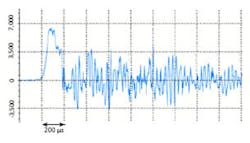
Figure 2 shows the time history of a typical shock intended to test high-velocity impact survivability of a military device. This recording was made on a machine similar in operation to that shown in Figure 1. The basic shock parameters of 6,500g peak amplitude at a duration of 200 μs can be seen in Figure 2. This type of shock is sometimes referred to as a pyroshock although pyrotechnic devices were not used in its creation.
The shape of the shock pulse is not a pure geometric fundamental, that is, not a half-sine, trapezoid, or terminal sawtooth. This lack of fidelity does not negate the test but rather complicates the determination of its validity because simple methods of evaluating the shock pulse shape cannot be easily applied.
This specification usually is given as a set of minimum SRS amplitude tolerance bars.3 Any deviation in amplitude of the actual shock test SRS below the tolerance limits may be considered a failed test.
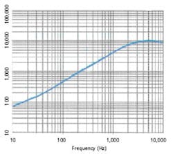
Figure 3 shows the SRS from the example shock parameters of Figure 2. Since the mechanical ringing of the product fixture was determined to be irrelevant in this case, the residual ringing trailing the primary pulse was truncated. The SRS then was computed from this adjusted time record. Although the time history shown in Figure 2 is not a perfect geometric half-sine shape, the resulting SRS in Figure 3 is almost indistinguishable from the SRS of a classic haversine wave shape.
In Figure 3, the peak of the SRS correlates with the 200-μs pulse duration. This type of analytical plot becomes a test specification if tolerance bars are superimposed over the SRS defining allowable deviation.
Conclusion
As products become miniaturized, requirements for shock machines and analysis methods change. Starting with shock durations needed to match product fundamental resonances while maintaining typical environmental ΔV values, shock amplitudes must increase. Increased ΔV capability is provided by miniaturized, acceleration-aided shock machines.
A miniaturized machine also can be stiffer. This stiffness shifts the machine’s self-resonances to higher frequencies, most probably out of the range that would overlap the resonances of the products.
Because of materials selection and design, product fixtures can be selfresonators and complicate fidelity of the test and data analysis. SRS is a solution to the data analysis part of this problem. In the presence of both machine and fixture resonances, SRS analysis can determine test adequacy, such as the product being subjected to the desired excitation.
Because of this capability and its test-to-test fidelity, SRS has become a standard method of verification in many product test applications. For the typical extreme short-duration shocks used for miniaturized products, SRS is the preferred analysis tool. However, SRS cannot overcome inherent machine performance limitations.
References
1. Smallwood, D.O., “An Improved Recursive Formula for Calculating Shock Response Spectra,” Shock and Vibration Bulletin, No. 56, Part 1, pp. 279-287. 2. MIL-STD-810-F, Environmental Engineering Considerations and Laboratory Tests, Department of Defense, United States of America. 3. Henderson, G.R., “A Proposed Method of Standardizing Shock Machines Using SRS Analysis,” Journal of the Institute of Environmental Sciences, July/August 1994, pp. 40-45.
About the Author
George Henderson founded GHI Systems in 1978. He holds a B.S.E.E. from Utah State University and has an extensive background in electronic, optical, and mechanical systems testing. GHI Systems, 916 N. Western Ave., San Pedro, CA 90732, 800-444-7978, e-mail: [email protected]
April 2002