Reading the Fine Print in a DMM Specification

Are you performing precision metrology? Does the seventh or eighth digit of a measurement really matter to you? If so, you already know that you need a high-resolution benchtop meter with good stability. Alternatively, there are 6½-digit PXI- and VXI-compatible DMMs intended for use in modular systems.
Generally, higher accuracy is found in meters with higher resolution, but not necessarily. And, although resolution is strictly a function of a meter’s design, measurement accuracy also depends on measurement technique. To make meaningful 8½-digit measurements requires considerable care and experience as well as a good DMM.
At the other extreme, many low-cost, hand-held DMMs may be suitable choices if you only require 5% accuracy and limited functions. A DMM may provide basic volts and resistance measurements, but if that’s all you need, it can be a good solution.
The people who must make much more difficult decisions lie between these two groups. They require higher functionality and accuracy than the one group but less accuracy, resolution, and lower cost than the other. These people have to understand how to read a data sheet if they are to make the best choice.
Footnotes
Many different benchtop DMM models are presented in Chart 1. Hand-held models are listed in Chart 2. Separating the two main types of meters is intended to help you find a suitable DMM more quickly. Both charts demonstrate the lack of uniformity among specification formats.
For example, DC voltage accuracy is specified as a percentage of reading plus percentage of range, a percentage of reading plus so many counts, or a percentage of reading plus so many volts. If you know how many counts are equivalent to full scale for a particular meter range, you can convert one format to another. All three types are found in the chart.
But, what about the test conditions that correspond to the claimed accuracy? A specification may read, “The stated accuracy is valid over the temperature range of 23°C ±5°C for one year.” Other common time periods are 90 days and 24 hours. DMM accuracies cannot be directly compared unless they are guaranteed for the same time period. In addition, a lengthy warm-up period often is required before the stated accuracy can be achieved.
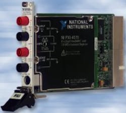
Some DMMs contain an integral reference and have a self-cal capability. This means they can be used without loss of accuracy outside of the standard 23°C ±5°C conditions. For example, the National Instruments PXI-4070 maintains its accuracy at any temperature within a 0°C to 50°C range following a self-cal run at that temperature.
Without self-cal, the accuracy specification must be derated if the instrument is used outside of the calibration temperature range. For example, consider a DMM with a temperature coefficient given as ±(5 ppm of reading + 1 ppm of range)/°C. Operating at 50°C rather than 28°C (the top end of a traditional 23°C ±5°C calibration range) incurs an additional measurement error of ±(110 ppm of reading + 22 ppm of range). This additional error may be much larger than the basic accuracy specification for some meters.
The footnotes for the charts add these types of qualifications to the fundamental accuracy figures. Six footnotes are given, but even 10 or 12 really wouldn’t be sufficient. For example, the frequency at which an AC voltage or current measurement is made affects the result. One manufacturer may segment the overall frequency range in one way and another manufacturer in a different way. The result is that a 60-Hz test frequency falls within a 10-Hz to 3-kHz band for manufacturer A and within a 45-Hz to 500-Hz band for manufacturer B. It takes more footnotes to tell the whole story.
The waveform crest factor also makes a difference. Crest factor is defined as the peak value divided by the rms value. Generally, high crest factors correspond to signals that only occasionally have large deviations from an average value. Higher crest factors are associated with higher measurement errors. A footnote may qualify an AC accuracy specification by restricting the allowable crest factor.
In addition to waveform shape, the size and speed of a signal must be within some limits or else the meter input circuitry can be damaged. For example, the Fluke 170 Series DMMs are limited to inputs having less than a 1 × 10⁷ V-Hz product. Although the meters have a 1,000-VAC range, the maximum frequency allowed at that amplitude is 10 kHz.
Measurement throughput and resolution are directly linked. For example, the Signametrics SMX2044 is described as a 6½-digit DMM. At that resolution, throughput is 30 readings/s. To increase throughput, you must reduce resolution. For example, as an option, this DMM provides 1,000 readings/s at 4½-digit resolution. A similar restriction applies to other manufacturers’ high-resolution DMMs. Additional footnotes are needed to tell the complete resolution vs. throughput story.
Meters with different full-scale ranges can be awkward to compare. For example, two meters may have voltage ranges scaled by factors of 10, but one range starts at 400 mV and the other at 1 V. For one meter, a 10-V measurement is full scale; for the other, it’s only 25% of full scale. The 400-mV meter will be on the 40-V range, while the other DMM will be on its 10-V range.
Resolution will be different by a factor of four between the two meters: no, not full-scale resolution but the actual resolution with which you can make the 10-V measurement. This means that noise may be objectionable on the 400-mV meter because an LSB is effectively four times larger than that in the 1-V meter when measuring a 10-V signal.
On very low-cost DMMs, an overall accuracy value may be listed with no qualification. When a representative of a company not included in Chart 2 was asked about this, he said that the accuracy of the instrument depended on how it was used. In any case, he recommended the DMM be recalibrated yearly. This fuzzy answer hardly inspires confidence and may be a good reason for the lack of detail on the datasheet.
Resistance
Resistance measurement is another area where specification detail varies greatly. In most cases, a current is forced through the unknown resistance and the resulting voltage measured. However, if the open-circuit voltage presented to the DUT is too high, problems may result.
For example, Tee Sheffer, the CEO of Signametrics, said, “Some DMMs we have looked at exhibit nasty behavior, such as having greater than a 10-V test voltage for ohms. In one case, this voltage stimulated the active circuit under test, causing oscillations and large measurement errors.”
The message is that the voltage applied to the DUT when making a resistance measurement must remain below a few volts. As an example, all ohms ranges of the Fluke Model 179 Meter have an open-circuit test voltage of less than 1.5 V.
Some DMMs are capable of eliminating voltage offsets while measuring resistance, making the ohms reading more accurate. Many types of resistances have a small voltage source associated with them. An example is the microvolt-level offset resulting from having dissimilar metals at different temperatures in the circuit being measured. A larger voltage, associated with EKG electrodes attached to a patient, is developed by the skin’s natural salts and moisture.
The so-called ohms offset function operates by making two measurements in succession, one with the resistance current source on and the other with it off. The voltage measured with the current source off is a voltage offset. It must be subtracted from the voltage measured with the current on. Then the correct resistance can be computed.
A technique that removes voltage offset and accounts for DUT self-heating makes successive measurements using two equal magnitude but opposite-polarity current sources. Rather than turning the current on and off, this method ensures a constant current magnitude for all measurements. If successive measurements are made within a few milliseconds, the DUT temperature and resistance will remain constant. This approach also can be shown to include 50% less noise in the computed resistance value than the simple voltage-offset correction method.1
Resistance measurements may be further qualified as using two wires, four wires, or six wires. In a basic two-wire configuration, the resistance of the wires connecting the DUT to the DMM is added to that of the DUT. The resistances cannot be separated. A four-wire, or Kelvin, connection sources current through one pair of wires and senses the DUT voltage via the other pair. Because very little current flows through the sense circuit, only the DUT voltage drop is measured.
Making four-wire resistance measurements works well, especially for low resistance values where the resistance of the connecting wires may be comparable to that of the DUT. For high resistances, however, leakage paths may exist in parallel to the DUT, causing some of the measuring current to be diverted. Guarding the DUT can eliminate this problem, although a guarded two-wire measurement is all that’s usually required on high-value resistances.
A DMM capable of six-wire resistance measurements has four-wire functionality plus guarding. This feature allows accurate resistance measurements to be made of one element in a resistor network, for example. The other resistors connected to the DUT are connected to the guard terminal. This effectively isolates the DUT from its surroundings. All three voltages—the voltages at each end of the DUT and the guard voltage—are provided with separate source and sense leads to avoid errors due to the resistance of connecting wires.
Typically, six-wire measurements are reserved for high-resolution instruments. A four-wire capability is much more common and extends into four- and five-digit DMMs. If no qualifying footnote accompanies the resistance specifications on a datasheet, you can assume that only a two-wire connection is provided.
Trends and Features
In addition to gradually improving voltage, current, and resistance measurement capabilities, the newest DMMs also are acquiring a variety of secondary characteristics. For example, the Keithley Model 2701 is based on a 6½-digit DMM but also includes expansion slots for input multiplexers and digital I/O cards. With the proper options, this DMM can measure and control DUTs in multiple test fixtures.
Improved functionality in the same volume as previously occupied by less capable instruments is attractive to test-system integrators. According to Qi Wang, Keithley’s manager of product marketing, “Keithley has taken advantage of advanced IC designs to pack more functions and higher performance into smaller instrument packages. The small scale of today’s ICs means that more of them can fit in a given space, which allows us to add a dedicated microprocessor to speed up and manage Ethernet data transfers.”
Continuing with the theme of Ethernet and associated LAN connectivity methods, Mark Bailey, a product marketing engineer at Agilent Technologies, said, “Connectivity definitely is an area of activity within the DMM industry. GPIB and RS-232 interfaces are being augmented by and in some cases replaced by LAN and USB interfaces.”
To find out what users require of DMMs, Fluke conducts research with end users. “Innovation comes in the form of mechanical as well as electrical and software engineering,” according to Chuck Bowden, the company’s senior product planning specialist. “In the latest DMMs, battery access doors and magnetic hook-and-loop hanging straps were identified as very important issues. Also, true rms instead of averaging AC conversion has been demanded because of the proliferation of nonlinear loads. Switching power supplies and adjustable-speed motor drives are taking over in industrial settings.”
Signametrics’ Mr. Sheffer, when discussing improvements to the company’s DMMs, commented, “Adding new algorithms to an existing DMM resulted in additional measurement and sourcing features. The expanded functionality, including temperature measurement, thermocouple linearization, and a very high-sensitivity DC current range with 10-pA resolution, allows the user to reduce the size and cost of the test system.”
In another example, National Instruments’ Kevin Bisking, the product manager for the NI PXI-4070 FlexDMM, said that a new architecture has enabled this single-slot, 3-U instrument to provide throughput varying from 100 readings/s at 6½-digit (22-b) resolution to 1.8 MS/s at 10 b. In addition, the very stable onboard reference and self-cal feature support a two-year calibration cycle rather than the industry-standard one-year interval.
And, innovative extensions are not limited to traditional DMM capabilities. For example, Omega Engineering’s OMEGASAYS® DMM features noncontact infrared temperature measurement guided by a built-in laser dot and circle. The temperature is announced to the user in a choice of five languages.
Perhaps this technology should be applied to eliminate the need for overly detailed DMM data sheets. When an input signal was connected, the meter could announce the value of the input together with all the qualifying frequency, temperature, crest factor, throughput, accuracy uncertainty, and volt-Hertz limitations. On second thought, perhaps not.
Reference
- Miller, C., Techniques for Reducing Resistance Measurement Uncertainty: DC Current Reversals vs. Classic Offset Compensation, Keithley Instruments, 2000.
Return to EE Home Page
Published by EE-Evaluation Engineering
All contents © 2003 Nelson Publishing Inc.
No reprint, distribution, or reuse in any medium is permitted
without the express written consent of the publisher.
February 2003
About the Author
Comment About the Article
To join the conversation, and become an exclusive member of Electronic Design, create an account today!

Leaders relevant to this article: