Thermal Management for Testing High-Power IC Devices

The most common approach to thermal management is the use of a heat sink. The choice of material is one of the main factors that affect heat-sink efficiency.
Aluminum’s light weight and low cost make it a widely used material for convection cooling. The highly conductive nature and significant low-spreading resistance of copper enable heat sinks produced from this material to efficiently spread heat along the base. This provides exceptional cooling for hot devices with high power densities. Copper heat sinks can increase heat dissipation from devices with heavy thermal loads by 10% to 20% compared to aluminum heat-sinks, but at an increased cost and weight.
Reducing thermal resistance for heat-sink optimization is becoming a critical task for engineers because of the increasing heat flux in high-performance IC devices.
Air cooling behaves in accordance with the principles of fluid dynamics, and heat-sink resistance can be calculated using the following equation:
Rhs = Rconductive + Rfilm + Rcaloric = (Ths base –Tamb) / P
Rhs = heat-sink thermal resistance
Rconductive = L/(k A) (conduction thermal resistance through the heat sink)
Rfilm = 1/(h h AN) (convection thermal resistance between the heat sink and the fluid)
Rcaloric = 1/(2r cp Q) (caloric thermal resistance due to heating of air as it flows through the heat sink)
Ths base = heat-sink base temperature
Tamb = ambient temperature
L = thickness
h = heat-sink efficiency
N = number of fins
r = liquid density
cp = liquid-specific heat
P = power (watts)
The equation shows that the thermal resistance of a heat sink can be reduced by decreasing one or more of the three component resistances: conductive, film, or caloric. However, the three definitions indicate that the resistance components are inversely proportional to the following parameters: thermal conductivity (k), the area of heat transfer (A), the convection coefficient (h), and the volume of air moving across the heat sink (Q).
For that reason, one or more of these parameters must increase to reduce the thermal resistance of a heat sink. While increasing these parameters appears relatively simple and inexpensive, there are limitations on the extent to which each can be increased for actual test applications. These limitations include factors such as:
- Environmental—noise level and vibration.
- Construction—installation space, inlet/outlet locations, and component accessibility.
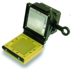
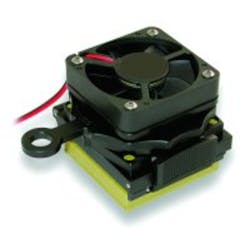
- Economic—costs of fabrication and assembly and external power required for supplemental cooling from fans or blowers (Figure 1, see below).
The principles of fluid dynamics for air cooling also apply to liquid cooling. But instead of removing heat by airflow, the heat is removed by the flow of a liquid, usually water. A liquid cooling system is more efficient than an air cooling system because the main resistance factors, caloric effect, and rise in the fluid temperature are much lower in a liquid cooling system.
A liquid cooling system acts as a heat exchanger where the heat output from the device under test (DUT) is extracted at a rate proportional to the specific heat and mass flow rate of the fluid. Water has an intrinsically higher thermal energy than air, and the mass flow rate of water can be easily controlled. A liquid cooling system yields a lower thermal resistance than an air cooling system, making it more efficient for thermal management.
A liquid cooling system, however, does have limitations. The effective temperature range for a water medium is limited to approximately 5°C to 95°C, the dynamic response is relatively slow, and temperature stability is low. There also can be condensation problems, especially in high humidity environments. But as with forced air cooling, liquid cooling is a relatively inexpensive method of thermal management.
A thermoelectric cooler (TEC) integrated with liquid cooling has evolved in recent years as a thermal management technique for test applications. TEC uses the Peltier effect to convert electricity to temperature differential. Its main advantages over air and liquid cooling are its wide temperature range of -100°C to +200°C and its capability to double as a heat pump and a cooler. Other TEC attributes include high reliability, rapid dynamic response, precise and stable temperature, small size, light weight, and relatively low cost.
A major limitation on the use of TEC alone arises from the amount of external power or supplemental heat required to extract the heat from the DUT. The low efficiency of TEC can be overcome by integrating it with an efficient heat sink such as liquid cooling systems. The result of combining TEC with liquid cooling is a thermal management system that combines the wide range, fast response, accuracy, and stability of the former with the efficiency of the later (see sidebar).
An alternative that provides the fastest response and greatest accuracy and stability for cooling is a refrigeration system. There are three drawbacks to widespread use of refrigeration systems for thermal management: they are expensive and large in size and have environmental issues because of the Freon used for cooling. The system also is limited to cooling applications, and a secondary heating circuit must be added for most test applications.
Thermal Management in Test Applications
The choice of a thermal management system depends largely on the specific test application. High power simulation, temperature characterization, and high-volume production testing are three applications that require thermal management for high power devices. However, each application has different degrees of accuracy, speed, and overall cost.
High-power simulation is used during the device development phase to quantify critical operational characteristics at specific temperatures and power data points over the operational temperature range. Because the data acquired during testing is used to establish operating specifications, accuracy and stability over the entire temperature test range are the critical aspects of thermal management during high-power simulation (Figure 2).
Offset precision of ±2°C at a 100-W thermal load over the operating temperature range of the device (usually -20°C to +80°C or greater) is sufficient to produce high-quality data for most high-power devices. This will enable the establishment of more precise operational specifications that will lower the out-of-tolerance rejection rate and produce higher yields during production testing.
Temperature characterization is used to determine operational characteristics of a DUT over a specified operating temperature range. The time to acquire data depends on the total time required to cycle through the temperature operating range. The dynamic response of a thermal management system is determined by its ramp rate, measured in °C/s. Ramp rates of 5°C/s and faster have been achieved, and this rate allows for characterization from -20°C to +80°C to be completed in 20 s or less.
High-volume production testing is a verification process rather than a characterization procedure, and accuracy is less critical. However, cost is of paramount importance.
In production testing, especially high-volume testing, total cost is a function of throughput and test-system cost. Thermal management for production testing is a value indicator, where a higher system cost can be justified if it results in a sufficient increase in throughput. For this reason, a thermal management system with a ramp rate of 5°C/s or higher vs. a system with a ramp rate of 1°C/s or lower will increase throughput significantly and may justify a higher price for some high-volume test applications.
Evaluating Thermal Management Methods
The variations in accuracy, range, speed, and cost of different thermal management methods mean that no single one will meet the objectives of every high-power test application. Rather, the method selected will be the one that best meets the critical requirements of a specific test application.
Table 1 (see below) provides a general, relative rating of the key selection criteria for the methods described.
About the Author
Jihad Hammoud, Ph.D., P. Eng., is the senior thermal engineer at Kulicke & Soffa. He has more than 10 years of experience in heat transfer, energetics, and thermal management. Dr. Hammoud received a Ph.D. from the University of Akron. Kulicke & Soffa, 3191 Corporate Place, Hayward, CA 94545, 510-782-2654, e-mail: [email protected]
A thermal management system developed by Kulicke & Soffa combines thermoelectric technology with active liquid cooling for rapid thermal cycling (heating and cooling) or regulating a steady temperature during test (Figure 3). The heart of the system is a thermal control unit (TCU) that houses a TEC and a resistance temperature device (RTD).
The TCU mechanically interfaces directly to the DUT using a manual latch or optional pneumatic actuator. The device case temperature is relayed to a two- or four-channel thermal controller connected to an external DC power supply. Each channel of the thermal controller drives a TEC for heating or cooling in response to the RTD feedback signal.
The heat is removed from the TEC module by water from an external recirculating chiller. This portion of the system effectively provides a feedback loop for controlling the temperature of the DUT. In addition, the TCU sends information to a data acquisition unit that can display test data on a monitor for real-time tracking and analysis or store the data in memory for future recall.
Return to EE Home Page
Published by EE-Evaluation Engineering
All contents © 2003 Nelson Publishing Inc.
No reprint, distribution, or reuse in any medium is permitted
without the express written consent of the publisher.
May 2003
About the Author
Comment About the Article
To join the conversation, and become an exclusive member of Electronic Design, create an account today!

Leaders relevant to this article: