Testing W-CDMA Signals Poses Many Challenges
Accurately testing the key RF parameters of wideband code division multiple access (W-CDMA) signals at any stage—R&D, manufacturing, or maintenance—poses quite a challenge. The reasons range from the infancy of the technology and the lack of a unified worldwide standard to the complexity of the signals.
To overcome these obstacles, test instruments are being developed with sophisticated hardware and dedicated software so accurate analysis of W-CDMA signals can be achieved in a cost-effective and expeditious manner.
The advanced hardware/software combination provides the capability to conduct some traditional R&D tests in a manufacturing environment. This is important because the tests provide an indication of potential problems or the need for slight adjustments due to component tolerances.
Simple pass/fail measurements are not effective enough to ensure the quality necessary for W-CDMA mobile phones or user equipment (UE) and base stations, known in W-CDMA as the Universal Terrestrial Radio Access Network (UTRAN). The goal for many manufacturers of
W-CDMA UE or UTRAN equipment is to detect any deviations that may result from a faulty component or part during the manufacturing process.
That is why the advancements in test hardware and software have become so important. To ensure that even the slightest deviation is detected in a W-CDMA signal, test instrumentation is designed with advanced platforms so analysis can be conduced at high speed.
These platforms integrate ASICs, special DSP technology, and a CPU that permits fast and repeatable measurements to be made. In fact, most test instruments designed to measure cellular phones have at least three processors: a DSP to measure signals and conduct averaging; a second processor to perform call processing, which allows the test instrument to act as a base- station simulator; and a third main processor to control the display, front panel, computer interfaces such as GPIB, and the other two processors.
The speed and power of the processors are two factors in determining a test instrument’s measurement speed. The other factors are the speed of the internal bus connecting the three processors and the software architecture and efficiency.
Dedicated software plays an important role in accurate W-CDMA signal analysis because there are two standards for W-CDMA. The initial standard was developed by NTT DoCoMo, followed shortly by the European standard, 3rd Generation Partnership Project (3GPP). Although 3GPP is expected to migrate to the United States, test solutions using dedicated software must conduct accurate and cost-effective analysis for both standards.
One of the most challenging elements in testing a W-CDMA UE is the signaling software. There are two methods in which a W-CDMA UE can be tested in manufacturing.
In the first method, a UE manufacturer uses proprietary test modes. This usually requires a special serial or USB connection to the UE so that commands can be sent to turn on the phone’s transmitter or receiver or to change channels. Occasionally, firmware has to be flashed into the phone so the UE can support the special test modes. This firmware can be costly and requires valuable engineering time that can be better spent developing new products.
With the other method, the test solution must act like a base-station simulator and transmit signaling messages over the RF link to control the phone. This method is preferred because it does not require special firmware to be flashed into the phone and allows for more thorough analysis because it tests the phone the way it will be used on the network.
Averaging Enhances Accuracy
To accurately conduct these measurements, a great deal of averaging must be done. While it takes more time to conduct averaging since multiple samples must be acquired, it does provide greater repeatability.
The higher the repeatability, the tighter the specification can be, which creates a number of advantages for the manufacturer. First, it can allow the use of lower-cost parts, reducing the cost of the end product. It also can result in higher yields that increase profitability.
The need for averaging also can depend upon the particular measurement, the device under test (DUT), and the stability of the DUT measurements. Also affecting the need for averaging is the wait time for the UE to stabilize after changing its input or output power.
In some cases, as many as 20 averages are used. Each measurement is an average of the measurements made on a single burst. Consequently, 20 averages would be the average of 20 bursts.

Twenty averages are being made on transmit power, frequency error, and occupied bandwidth. The filtered power measurement is of power filtered through the root raised cosine filter that the UE and UTRAN have on their receivers.
These are just some of the measurements performed on W-CDMA UE and UTRAN. A list of the key transmission, reception, and call-processing measurements can be seen in Table 1 (see below). These tests are specified in the 3GPP 34.121 Terminal Conformance Specification.
Table 1. Key RF Measurement Items for W-CDMA
Terminal Conformance Specification
Fast Measurement Time
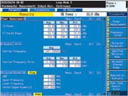
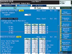
Despite the complexity and the number of different measurements that must be conducted, analysis can be performed quickly. One reason for the fast measurement speed is the capability to conduct measurements simultaneously, as shown in Figures 1 and 2.
This capability and the advancements made in instrumentation design allow transmitter (TX) measurements, which include output power, frequency error, occupied bandwidth (OBW), spectrum emission mask, adjacent channel leakage power, error vector magnitude (EVM), and peak code domain error (PCDE), to be conducted in as little as 200 ms. A complete test of a UE in manufacturing, including handling time, call processing, inner-loop power control measurement, and TX and receiver (RX) measurements at several channels and at several output levels, takes about 69 s.
R&D design verification testing makes these measurements at every channel and adds interfering signal generators for additional receiver tests and 30-GHz spectrum analyzers for measuring up to the 10th harmonic of the transmitter. In a manufacturing line, the tests will be conducted at one to three frequencies per band supported by the UE.
Aftermarket applications are slightly different since access to the special test modes and fixtures often is not available. Even if it was, it usually is too much trouble to change test systems to suit the special test-mode commands for each phone and manufacturer. So, controlling the phone with the call-processing signaling of the network is the only practical way.
Conclusion
The complexity of W-CDMA signals makes conducting accurate measurements difficult. To ensure quality, tests done at the R&D level also must be conducted during manufacturing, only at a faster and more cost-efficient rate.
As a result, test solutions have been developed to address multiple standards and detect the slightest drift in signal integrity. Because they are single-instrument solutions, W-CDMA UE manufacturers can conduct multiple measurements quickly and efficiently, meeting the market demand for quality and price.
About the Author
Craig Hendricks is a senior technical support engineer at Anritsu. He has been involved in wireless test for nearly 20 years. e-mail: [email protected]
Return to EE Home Page
Published by EE-Evaluation Engineering
All contents © 2003 Nelson Publishing Inc.
No reprint, distribution, or reuse in any medium is permitted
without the express written consent of the publisher.
August 2003
About the Author
Comment About the Article
To join the conversation, and become an exclusive member of Electronic Design, create an account today!

Leaders relevant to this article: