
This year, there are many more ways being developed to reduce the cost of test than there are ATE companies. In anticipation of the elusive economic upturn, recently introduced testers and updates to existing ones continue to reduce the cost of test while simultaneously addressing more stringent technical requirements. And, there are many other innovative ways in which increased value is being delivered.
Several manufacturers of so-called big-iron testers have standardized on single platforms. This approach alters the buy/depreciate/obsolescence equation by ensuring future upgrade compatibility with legacy testers and test programs. In addition, greater circuit integration in instruments for automated test has helped to lower production costs, resulting in higher performance at prices comparable to those of earlier, slower models.
Higher numbers of pins are required for new system-on-a-chip (SOC) packages, but a greater pin-count also facilitates parallel test of multiple devices. The vice president of technology at LTX, Neil Kelly, commented that some customers now are specifying multiple-site test on the initial purchase orders. In previous years, the multisite capability was added later as production volume ramped up.
Design for testability (DFT) generally relates to IC design, but it also affects ATE. Testers that are DFT-aware integrate built-in self-test (BIST) resources into the ATE architecture. Virtual tools that access the on-chip BIST circuitry are seamlessly merged into the ATE software. There is no operational distinction between the use of these tools and instrument hardware and software within the actual tester.
A new class of DFT testers may drastically reduce the cost of test. Rather than perform functional testing by accessing all of an IC’s I/O pins, a DFT tester uses the SCAN port connections. If an IC design has made extensive use of DFT techniques, there may be no need for more than a DFT tester in production. Teseda, a manufacturer of DFT-focused ATE, forecasts an initial use model that combines a DFT tester at wafer sort with conventional ATE performing final functional tests on packaged parts.
Many companies have their own views of what constitutes an open architecture (OA). But without a single definition, the economy of scale promised by OA proponents won’t occur. Nevertheless, the Advantest-led Semiconductor Test Consortium (STC) continues moving forward, and at least one ATE company has separately announced a platform with an OA.
The problems are more economic than technical. How should OA ATE be configured if it is to be economically competitive with existing proprietary solutions across the range of price points presently served? An OA can be designed and all the software and hardware interfaces specified. Third-party instrument makers and software developers can provide products that will operate in such an OA ATE. But, will it be profitable for them to do so?
Single Platforms
The use of a single, scalable platform has many advantages from a manufacturer’s point of view. Within limits, such an architecture can address a wide range of speed and complexity requirements without redeveloping the tester chassis, power supplies, system software, and user interface.
“The Agilent Technologies 93000 SOC Series ATE is a single, scalable platform,” said Gordon DeWitte, an Agilent product marketing engineer. “It increases asset utilization by covering a range of applications, simplifies our customers’ manufacturing floors, and provides a long lifetime for the asset because of the product’s expandability.
“Port scalability allows a few high-speed channels to be added to a low-cost tester, matching the tester capability to the application requirements and minimizing cost. In addition to multisite test,” he continued, “the 93000’s concurrent test capability provides significant test time savings. The tester has up to 64 independent ports, yielding a very high level of concurrent test.”
Additional product features include background processing to speed up measurement time, a test processor-per-pin architecture to reduce setup time, and a wide selection of instruments to support applications from DC to RF. The tester also can perform test-vector compression/decompression to minimize pattern memory requirements.
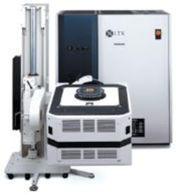
LTX recently introduced the Model HFi, the latest tester built on the Fusion platform. It uses the same architecture and operating software as previous Fusion testers, but the hardware performance has been significantly improved to cope with more stringent SOC test requirements.
Much of the tester’s circuitry has been integrated, resulting in an 85% reduction in IC count. Four digital channels are controlled by a large CMOS ASIC in combination with two GaAs timing chips, two dual-channel bipolar driver/receiver chips, and a number of RAMs. The custom chips include glue logic, so the physical size of the circuitry really does shrink dramatically. As a consequence of the chip design and short path lengths, the Fusion HFi achieves a 2.5-GHz data rate per pin.
Equally as important as speed, the new hardware deals with source-synchronous SOC designs. In a traditional synchronous system, a single clock is distributed with as little skew as possible across the clock tree structure. Timing tolerances may become so tight in large and very fast designs that zero-skew clock distribution proves to be an impractical objective. Instead, a source-synchronous design can be used that distributes the clock with the data.
In a multidrop backplane design, for example, each daughter board would receive data relative to a specific clock signal. This clock is associated with the received data and not necessarily in phase with clocks on other daughter boards.
In a comparison of synchronous and source-synchronous systems, Fairchild Semiconductor developed an example that showed a 150% speed improvement. Using a private clock version of a source-synchronous system, a maximum data rate of 142.8 MHz was possible vs. 59.9 MHz for a traditional synchronous approach.1
In a complex SOC, source-synchronous clocking may be used to achieve high-speed operation of several separate data ports. In this case, each port corresponds to a separate clock domain. The tester clocks must run as slaves to the individual port clocks rather than as independent clock sources. This type of operation is aided by the variable clock speed element of the Fusion architecture.
While the single-platform strategy has some attractive benefits, it is not the approach being taken by all ATE manufacturers. Phil Smith, a strategic marketing manager at Teradyne, explained that the company develops separate models to serve distinct market segments.
Although it makes sense to collapse as many products as possible into a smaller range with common parts and software, Mr. Smith explained that, in Teradyne’s view, a single platform is too restrictive. “The goals of [having a single platform] are correct, but the single-platform approach carries infrastructure baggage and configuration problems that can drive up the cost of each tool, reducing the benefit. The fact that about six times more market-focused systems were sold in the last five years than single-platform machines seems to bear this out.”
In Figure 1, the importance of performance, time to market, and cost of test is shown in relation to tester characteristics and types of devices being tested. The large variation in the curves is the reason that single-platform testers must be very flexible. Alternatively, Teradyne has chosen to address significant market segments with more specialized machines.
DFT
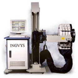
“It is estimated that more than 95% of new designs use full scan DFT test techniques,” according to Peter Hwang, director of marketing at Inovys. “This shift toward structural test is dictated by the increasing complexity of the designs and time-to-market pressures requiring faster product validation and release to production.
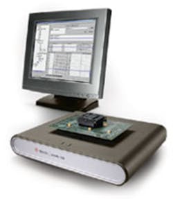
Many of the major differences between DFT testers and conventional ATE are discussed in a white paper by Steve Morris, CEO and president of Teseda. In DFT-focused testers, cost is reduced in four ways:
- Fewer tester pins are required because, in addition to power and ground, only the scan I/O and control pins must be contacted.
- Compared to the high-speed requirements of a functional test pin, the relatively relaxed scan data and clock rates can be satisfied at lower cost.
- If only a portion of the total number of DUT pins needs to be contacted, the probe card can be less expensive.
- Multisite testing makes the best use of the expensive wafer prober.
In both the Teseda and Inovys products, STIL, the IEEE 1450/1999 test interface language, is used to communicate with ATPG tools. Not needing to translate from STIL to another language or format avoids the possibility of introducing errors when importing test patterns. The advantage of directly using STIL-formatted data is not as trivial as it may sound.
Popular ATPG tools output cyclized test patterns in STIL or waveform generation language (WGL) formats. Because the test vectors already match the cyclic nature of the test process, translation is not difficult. However, the general test-development problem is much harder to solve when starting from design simulation files in formats such as Verilog change dump (VCD), which do not directly relate to test needs.
In this case, translation reorganizes the test-pattern information to match the characteristics of a particular tester. The process involves cyclization and reformatting and can be affected by a large number of user options. Simplifying these broad issues has been the motivation behind adoption not only of STIL, but also the P1450.6 core test language (CTL) and the IEEE 1364 Verilog hardware description language (VHDL).
In a related effort, LogicVision has formed alliances with leading ATE and electronic design automation (EDA) companies to further the use of BIST tools. The LV Ready Program supports integration of LogicVision embedded test solutions in test systems.
For example, Credence Systems was one of the first ATE companies to develop software making its testers LogicVision-ready. “LogicVision’s embedded test capabilities run directly from Credence’s Quartet Test Systems for full access and control of embedded test resources within the DUT,” said Marc Loranger, senior director of marketing at the company. “Test engineers can save time by initiating go, no-go production or interactive tests to diagnose device failures.”
Similarly, Teradyne, in conjunction with LogicVision, has integrated a test tool into Catalyst’s IMAGE Software that gives test engineers a means to communicate directly with the BIST circuitry embedded in the device for both production-level pass/fail test and detailed structural test diagnostics. BIST and the BIST Access Tool provide a means to perform high-quality structural test for SOC devices and at the same time simplify the test development process by automatically creating the required digital test patterns.
OA
When asked to comment about the OA movement at ITC 2002, representatives of many ATE companies countered that they already had platforms based on OAs. Closer examination revealed that they actually meant open standards: systems open to instruments meeting published, but proprietary, requirements.
The standardization occurring within the ATE industry is around a small number of specific platforms, not a single, abstracted specification. One example is LTX’s Fusion HFi Tester. According to the company, “Fusion’s open platform enables LTX’s development partners to speed additional, fully integrated instruments to market.”
- It is very low cost, yet has a scalable infrastructure.
- Having no backplanes or complex power distribution or signal harnesses makes the system easily field reconfigurable by the customer. This allows system redeployment for different SOC applications and maximizes capital re-use.
- The same platform can be configured for test applications ranging from device debug and characterization to low-cost production, including DFT-enabled devices.
- A high throughput with built-in, multithreaded parallel test capability supports efficient parallel test of devices, even if they require complex test flows.
- It has an OA with well-defined instrument encapsulation guidelines that facilitate third-party additions to the platform.
Conclusion
There’s no doubt that the ATE industry is changing. However, the influence of each new trend isn’t at all obvious. In the short term, Teradyne’s Mr. Smith was confident that more flexible scan structures within chips and the need for very deep fail-capture memories in testers were important factors. For example, in Teradyne’s new highly configurable FLEX tester, the fail-capture memory was increased to 3 GB from 1.5 GB on the earlier Tiger tester.
Speculating about the future shape of ATE is another matter. Although many logic testers can operate at multigigahertz speeds, new chip and system designs are incorporating more high-speed serial data buses than in the past. It’s possible that a paradigm may develop that emphasizes bus structures and significantly reduces the need for bulk digital pin capabilities running at more than 500 to 600 MHz.
If this occurs, deep test-vector memory associated with high-throughput scan testing will form the core of most digital testers. Very high-speed capabilities for a few data ports can be added much like analog capabilities are provided today for a few pins. The end result will be much different and cost less than many current testers that boast of ever-increasing speed and memory depth for every pin.
But just changing the tester isn’t the entire answer. “As the complexity of SOC and other advanced ICs has drastically increased, the total cost of test also has risen. As much as 75% of the total test costs, including test program development, simulation, characterization, debug, and training, now are in noncapital equipment costs,” said Credence’s Mr. Loranger. “Manufacturers are under tremendous pressure to bring products to market quickly with the lowest possible cost. We believe that improving the design-to-production test flow is one of the most optimal ways to meet their needs.”
As Mr. Smith concluded, “It is looking like the future will be a most interesting time. Perhaps we will see the return to growth that we are all looking for.”
References
- How Source-Synchronous Clocking Increases Bandwidth in Parallel Backplanes, Fairchild Semiconductor, 2002.
FOR MORE INFORMATION
on single-platform SOC ATE
www.rsleads.com/308ee-177
www.rsleads.com/308ee-178
on DFT testers
www.rsleads.com/308ee-179
www.rsleads.com/308ee-180
Return to EE Home Page
Published by EE-Evaluation Engineering
All contents © 2003 Nelson Publishing Inc.
No reprint, distribution, or reuse in any medium is permitted
without the express written consent of the publisher.
August 2003
About the Author
Comment About the Article
To join the conversation, and become an exclusive member of Electronic Design, create an account today!

Leaders relevant to this article: