Automotive EMC Immunity Specs Strike a Chord
The Big Three automakers are working together to develop a single document that will reduce the test burden on suppliers.
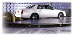
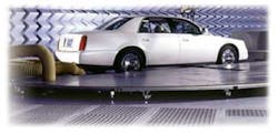
Courtesy of ETS-Lindgren
Automakers in the United States have not yet achieved harmony in their standards for radiated and conducted EMC immunity testing, but the latest revisions to specifications from Ford Motor Co. and General Motors are a big leap in that direction. The revisions simplify testing and narrow the gap between the requirements of both companies. For suppliers, this should translate into reduced test costs since the number of tests will be decreased along with the equipment and time required.
In some industries, competition and proprietary solutions have resulted in multiple, incompatible measurement specifications in which the twain only occasionally meet. Only through a long process of sometimes heated debate have universal standards been achieved.
In these situations, the champion of each potential standard has much to gain from seeing its process universally adopted. In contrast, proprietary automotive EMC immunity specifications benefit no one since a supplier to GM, Ford, and DaimlerChrsyler, for example, must certify its products for three different sets of requirements.
As a result, engineers at the Big Three have been increasingly working together, especially since the fall of 2001, to reduce the test burden on suppliers. The goal is to arrive as quickly as possible at a single document in which all testing would be common.
For example, a component used by GM also could be used by Ford or vice versa without retesting since Ford would accept the data produced for GM as proof of performance. This is not an altruistic endeavor: Reduced testing can potentially reduce automaker component costs.
Checking Reality
In the past, Ford and GM have tried to ensure their vehicles were unaffected by every conceivable RF source through broad-based contiguous limits. This is an exceedingly difficult task, one that the companies have decided is unnecessary since many emitters are at too low a level or access to them by the motoring public is highly unlikely. Instead, the automakers focus on the sources that have or could potentially impact the vehicle’s electronic systems.
Establishing more realistic and, from a test standpoint, more readily achievable specifications has taken different routes at Ford and GM. Over the last few years, Ford saw an increase in potentially hazardous emitters such as high-power radars, wireless phones, GPS, and wireless LANs.
Even Bluetooth-enabled devices such as hands-free phones, which emit a very low level of radiation, are finding their way into vehicles. To anticipate the current and impending electromagnetic onslaught, Ford raised the frequencies at which radiated immunity testing must be performed from
1 GHz to 3.1 GHz.
GM previously mandated testing to 10 GHz. However, after evaluating the potential emitters, mostly radars, at higher frequencies, GM lowered its maximum measurement frequency to 2 GHz. The change is significant because test cost and complexity increase directly with frequency.
The recent changes from Ford and GM bring the EMC requirements of the two companies closer than before and, while not exactly the same, are close enough that most test equipment for one should suffice for the other. The test procedures and hardware mentioned in this article are defined in Table 1.
|
Test Procedure |
Definition |
| Parallel-Plate | Electric fields generated by test system; radiated by parallel- plate antenna; conducted in shielded chamber; used for radiated immunity testing of relatively small components placed between two plates of antenna |
| Absorber-Lined Chamber (ALC) |
Establishes an indoor EMC facility simulating open-field testing; consists of shielded room lined with absorbing material to minimize reflections and resonances to -10 dB or less; referred to in current standards as absorber-lined shielded enclosure (ALSE) |
| Bulk Current Injection (BCI) |
Induces disturbance signals directly into a wiring harness using current injection probe; tests performed by varying level and frequency of injected signal; conducted in shielded room |
| Triplate Line (TPL) | Variation of transverse electromagnetic (TEM) cell minus sides to accommodate large devices with cables, eliminating feedthrough ports or adapters required when using TEM cell; handles higher frequencies than TEM cell; must be used in shielded room |
| Reverberation Chamber |
Shielded enclosure using reflections set up inside high-Q metallic room; mechanical tuners or stirrers used to mix or stir electromagnetic field |
| Mode Stirring | Performed in reverberation chamber where rotating stirrer changes positions of maximums in electromagnetic field (also called modes) throughout chamber within one revolution; single frequency applied, paddle rotated 360°, and process continued over required frequency range |
| Mode Tuning | Similar to mode stirring except paddle stationary while frequency varied over required range; paddle stepped to next position, frequency varied again, continued until paddle traversed 360° of rotation and all frequencies tested |
Table 1. EMC Test Procedures
Streamlining at Ford
The changes in radiated immunity specifications at Ford, detailed in ES-XW7T-12A278-AC, the Ford Motor Company Component and Subsystem Electromagnetic Compatibility Worldwide Requirements and Test Procedures document issued Oct. 10, 2003, are more comprehensive than in GM’s GMW3097 EMC test specification The previous Ford document had TPL testing as its preferred method. If TPL testing could not be performed across the entire range of frequencies, any combination of stripline, BCI, or parallel-plate testing or an ALC could be used.
What might be regarded as a high level of flexibility in practice provided too many choices. In addition, Ford engineers believe that they should be in a position to technically support any requirement they impose. A reduction of certain tests would allow them to focus on methods in which they have considerable expertise.
Ford eliminated the triplate, stripline, and parallel-plate tests in favor of BCI testing for frequencies from 1 to 400 MHz. The frequency range from 400 MHz to 3.1 GHz is covered by the ALSE test method.
The reverberation chamber, with which GM has considerable expertise, also was included. Ford incorporated this method as an alternative to ALSE. TPL was eliminated because its viability was stretched at frequencies above 1 GHz, and stripline was removed because it was deemed unsuitable for testing large objects such as digital instrument clusters.
Ford’s changes to conducted immunity transient tests are perhaps even more wide-ranging since they depart from the approach that generally is accepted by most automakers. Ford had been using ISO 7637 Part 2 standard for transient immunity. Within it are standard pulse waveforms used almost universally throughout the industry.
In the process of developing 42-VDC design standards that will be implemented in the near future, the company researched the work in transient testing in the automotive and telecommunications industries going back 60 years. Ford engineers learned a great deal about contact arcing and the transients it produces and came to the conclusion that the current ISO and SAE waveforms were inadequate. Ford found that the waveforms either indicated problems that did not exist in the vehicle or, worse, failed to identify issues that were later discovered when the vehicles were in service.
To more accurately simulate conditions encountered in the field, the engineers decided that the actual waveforms produced by mechanical switching of an inductance should be used. The waveforms better represent the nonrepetitive waveforms encountered in the automotive environment. There is variability in timing and voltage from event to event, and the coupling mechanisms are considerably different than those produced by the standard waveforms.
In the revision, Ford retained all but two of the ISO waveforms because, before they can be replaced, there must be discussion and peer review by all three automakers. The mechanically switched waveforms then might replace the standard waveforms.
Since Ford engineers had been researching this issue long before the three U.S. automakers began to discuss it together, they were in a position to incorporate pulse changes in this revision. While GM engineers appear interested in the information provided by Ford, they will need to study the data further before making a decision.
The Latest From GM
GM’s most obvious step toward simplification is reducing the number of standards from two to one. GMW3097 Revision 4 General Specifications for Electrical/Electronic Components and Subsystems, Electromagnetic Compatibility (EMC) was introduced Dec. 3, 2003. It consolidates the company’s two EMC compliance documents, GMW3097 and GMW3100, which actually has the same title as GMW3097. The test requirements previously were contained in GMW3097 and the procedures in GMW3100.
The company has long-term experience with reverberation test chambers, especially with the mode-stirred technique. However, since the International Electrotechnical Commission (IEC) is leaning toward mode tuning in reverberation chambers, GM decided to move to it as well. While both the mode-stirred and mode-tuned techniques can be used as alternatives to the ALSE test method today, the mode-stirred technique will be phased out by July 1, 2005.
BCI testing is similar to GMW3097 Revision 3. The break point between certain frequency bands differs slightly, and the injected current level at 1 MHz has been reduced. In addition, the required levels for immunity to EM fields for components and subsystems measured in an anechoic chamber also are substantially changed from Revision 3.
The earlier revision required testing from 400 MHz to 10 GHz in eight discrete frequency bands. Revision 4 consolidates the radar test bands from five to two and reduces the upper test frequency from 10 GHz to 2 GHz.
GM made fewer changes to conducted immunity transient testing specifications. Direct capacitor coupling for input and output lines now is an option, and for ESD testing, the number of discharges has been reduced.
Waves of the Future
The trend in automotive EMC is to harmonize standards, at least among the three U.S. automakers. While DaimlerChrysler has not yet produced a document that is as “harmonious” as that of Ford and GM, it is largely a matter of timing.
In 2002, the company produced a global EMC specification that applies to all DaimlerChrysler brands as well as Mitsubishi. Although it completed its document before Ford and GM, the company still incorporated what changes it could from these two companies. For Ford and GM, the timing was excellent, since both companies were on schedule to produce revisions at about the same time.
The informal goal of all three automakers is to have a very nearly harmonized document in as little as two years. This ambitious goal should be achievable because the engineers at all three companies work closely together, meeting monthly, and serve on national and international committees. Most have known each other for years.
For suppliers accustomed to making multiple measurements, a thoroughly harmonized EMC specification would be a significant improvement and, for the automakers, an inducement to keep component costs down. To what extent these goals are realized should be evident soon.
Acknowledgment
The authors wish to thank Laura Ball of General Motors and Keith Frazier at Ford Motor Co. for their help in preparing this article.
About the Authors
Pat Malloy has been the sales application engineer at Amplifier Research, now AR Worldwide, since 1987. Previous work experience includes four years with the U.S. Navy as a guided-missile electronic technician, seven years in an engineering group at AT&T Bell Laboratories, and 16 years as a senior sales engineer for Tektronix. He graduated from Lafayette College in 1972 with a B.S.E.E. e-mail: [email protected]
Thomas C. Moyer is marketing specialist at AR Worldwide. He has worked for Ford Motor Co. designing automotive electronics systems and for Ametek U.S. Gauge developing aircraft engine instruments. More recently, he was a sales engineer and regional sales manager. Mr. Moyer received a B.S.E.E. from Drexel University. e-mail: [email protected]
AR Worldwide, 160 School House Rd., Souderton, PA 18964-9990, 215-723-8181.
Return to EE Home Page
Published by EE-Evaluation Engineering
All contents © 2004 Nelson Publishing Inc.
No reprint, distribution, or reuse in any medium is permitted
without the express written consent of the publisher.
March 2004
About the Author
Comment About the Article
To join the conversation, and become an exclusive member of Electronic Design, create an account today!

Leaders relevant to this article: