There are some very significant differences between individual NEBS and European standards you need to know before you start testing.
The network equipment building systems (NEBS) re-quirements have been established to ensure that new telecommunications equipment is suitable for deployment. This very broad statement covers performance aspects such as EMI/EMC; environmental including vibration, temperature, and seismic shock; and safety, especially the product's propensity to burn when subjected to stringent flame tests.
NEBS testing evaluates equipment separately, for example, with regard to lightning discharge. Each new product must exhibit an established level of immunity to simulated lightning surges. In addition, equipment must be compatible with existing central office (CO) installations. The capability of equipment to operate within existing CO heat-dissipation guidelines is related to CO safety because overheating could cause a fire.
The group of tests referred to as NEBS is not new, having been defined by Bell Laboratories in the 1970s and updated as the standards organization changed to Bellcore and now Telcordia. Similar European test standards exist, many with similar intentions but not necessarily identical definition or implementation.
Two areas of NEBS testing will be discussed: the lightning surge-test requirement variations, which compare subtle but significant differences in measurement definitions; and temperature, humidity, and heat dissipation, which highlight the unintended consequences of using today's much more compact telecommunications products.
Lightning Surge Test Requirement Variations
In today's highly competitive markets, it's only prudent to develop products that meet both NEBS and European lightning surge test specifications. For NEBS, the standard is GR-1089-CORE (Issue 2, December 1997, Revision 1, February 1999), Section 4 Lightning and AC Power Fault. In the European Union, the lightning surge requirement is EN 61000-4-5 Surge Immunity Test.
For both specifications, the requirements are the 1.2/50-'s voltage waveform and the 8/20-'s current waveform. The waveforms defined by the two standards appear to be the same. The test methodology uses similar instrumentation, calibration, and application procedures.
But aside from the obvious differences in test severity levels, a closer evaluation proves otherwise. There are notable dissimilarities between the individual standards, and proper planning is required if you are trying to use the same surge generator for both the GR-1089-CORE lightning test and the EN 61000-4-5 surge immunity test on AC power inputs.
In short, both standards define the 1.2/50-'s voltage waveform as an open-circuit waveform with a rise time of 1.2-'s and a fall time of 50-'s and the 8/20-'s short-circuit current waveform having a rise time of 8-'s and a fall time of 20-'s. At this point, let's take a closer look at the definitions of rise time and fall time between EN 61000-4-5 and GR-1089-CORE Section 4.
EN 61000-4-5
Rise Time
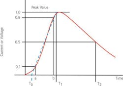
The interval of time between the instants at which the instantaneous value of a pulse first reaches a specified lower value and then a specified upper value. Unless otherwise specified, the lower and upper values are fixed at 10% and 90% of the pulse magnitude.
Surge Voltage
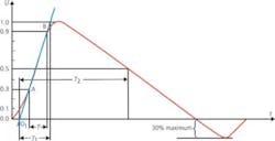
The front time (T1) of a surge voltage is a virtual parameter defined as 1.67 times the interval T between the instants when the impulse is 30% and 90% of the peak value (Figure 1).
Figure 1. EN 61000-4-5 Open-Circuit Voltage (1.2/50-'s) Waveform
T1 = 1.67 • T = 1.2 's 30%
T2 = 50 's 20%
Current Surge
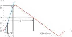
The front time (T1) of the surge current is a virtual parameter defined as 1.25 times the interval T between the instants when the impulse is 10% and 90% of the peak value (Figure 2).
Figure 2. EN 61000-4-5 Short-Circuit Current (8/20-'s) Waveform
T1 = 1.25 • T = 8 's 20%
T2 = 20 's 20%
Fall Time
Defined as Time to Half-Value (T2). The T2 of a surge is a virtual parameter defined as the time interval between the virtual origin (O1) and the instant when the waveform has decreased to half the peak value (Figures 1 and 2).
GR-1089-CORE Section 4 Lightning and AC Power Fault
Rise Time
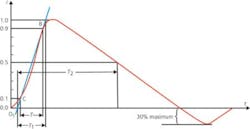
The rise time of the generator is calculated by measuring the duration between 10% and 90% of the maximum pulse amplitude and multiplying that value by 1.25 (Figure 3).
Fall Time
The decay time is calculated by measuring the time from the initial rise of the waveform to the point where it decays to one-half of the maximum value (Figure 3).
a = Front Time = 1.25 (b-a) = T1 – T0
b = Duration = (T2 – T0)
Appendix A
The rise time stated in GR-1089-CORE is the maximum rise time permitted and allows for rise times of shorter durations. The decay time is the minimum decay time permitted and accommodates for decay times of longer durations. If you compare the tolerances from EN 61000-4-5, you will notice the rise times and fall times for both voltage and current allow a plus and minus tolerance. GR-1089-CORE only allows for a maximum value for voltage and current rise time and a minimum value for voltage and current fall time.
This issue will become more prevalent as manufacturers and test labs performing to EN 61000-4-5 begin testing to the GR-1089-CORE standard. The differences between the two stand-ards were apparent when Garwood Laboratories completed a recent audit by one of the largest telecom carriers in the United States. The surge generator purchased by Garwood was designed to meet the more stringent guidelines of GR-1089.
There is an important point here: If you are going to test to the lightning surge test per GR-1089-CORE and EN 61000-4-5, be aware of the differences in the tolerance for both the rise and the fall times of the two standards.
Temperature, Humidity, and Heat Dissipation
The temperature, humidity, and heat dissipation specified in GR-63-CORE not only cover the criteria for equipment in operation, but also in its packaged state. Like all cargo shipped in boxes, the temperatures the unit may encounter will vary by region.
NEBS GR-63 takes this into account and includes three separate package tests with temperature and humidity in mind. The low-temperature exposure and thermal-shock test introduces the packaged unit to a steady-state temperature of -40 C for a minimum of 72 h. A real-world comparison would be the packaged unit sitting in a warehouse for a prolonged period of time in a cold region. The temperature then is transitioned to an ambient of 25 C within 5 min. In most cases, the packaged unit is simply removed from the test chamber.
This provides the temperature shock much as there would be if the unit is shipped from a warehouse, placed into a truck, driven to the drop point, removed from the truck, and placed into a temperature-controlled environment. The unit is expected to operate as it would in its intended in-service function after being subjected to this environment.
A high-temperature exposure and thermal-shock test is performed similar to the low-temperature test, but the unit is subjected to an environment of +70 C for the same minimum 72-h duration and the same 5-min transition time to ambient. Again, we are looking at the capability of the equipment to operate as required after this exposure.
There also is a high relative humidity (RH) exposure test that subjects the packaged unit to a 96-h dwell at +40 C and 90% to 95% RH. In this test, the temperature is transitioned from +40 C, 90% to 95% RH back to ambient (25 C) at a rate of 30 C per h. The unit then is verified for proper operation following the high humidity exposure.
These tests can and many times are performed back-to-back before checking the operation of the unit since years of test experience prove that the failure rate after performing these tests is extremely low. Credit the manufacturers and packaging departments for doing their job well.
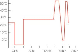
Getting into the operational characteristics of the unit, GR-63 provides an operating temperature and humidity test. It is designed to ensure the unit will operate under different temperature and humidity environments in the CO.
The CO is an environmentally controlled atmosphere. But what happens when the power goes out and the HVAC system shuts down? That depends on where you live. If you are in the southern United States in August, it certainly will heat up and most likely become very humid. If you are in the Northeast in January, then it will get quite cold. How about Arizona? Hot and dry, for sure.
GR-63 takes all this into account and provides a profile that addresses these various possibilities. The equipment under test must continue to operate when subjected to the test profile shown in Figure 4. This means there must be zero downtime from the start through the completion of the test.
Figure 4. Profile for GR-63 Operating Temperature and Humidity Test
All traffic should be captured during the test, and certainly an error log should be available to review potential failures. Since the test is about 182 h long, it is tough to find someone to sit in front of the chamber and watch for errors the whole time.
The EUT's capability to maintain operation during these conditions is all part of the telecommunications five-nines (99.999%) reliability statement. There is a good reason why, when natural disasters occur, the phone system almost never goes down.
Heat dissipation, or heat release, is and probably will be for quite some time a major issue for the telco industry. Think about the older equipment that the COs had, with the big switch systems like the 5ESS that took up a whole rack space with large circuit cards.
Now, think of what we have in the COs like some of the DSL technologies. A 1U box is common with DSL deployment. That 1U box encompasses a great deal of flexibility, but there is a price to pay. They are very high heat-generating boxes.
The component layout in a simple 1U box could generate upwards of
300 W of heat. Let's say the 1U box measures 12″ D • 1.75″ H • 23″ W. Using the calculation of determining the heat release of a -48-VDC system that generates 300 W mounted in a standard 23″ telco rack gives us a value of 287 W per ft2 per vertical ft of rack space. I may be wrong, but that could exceed the maximum value for forced air-cooled shelf-level systems of 27.9 W per ft2 per vertical ft.
To meet the value of 27.9 W/ft2/vertical ft, that unit would need an additional 18.36″ of space in the rack to properly release the heat generated. Can you imagine a test rack with a 1U box taking up essentially 20″? Nope, it just doesn t happen.
If you have the chance to attend any of the NEBS seminars sponsored by Telcordia Technologies or Verizon, you will see some of the extravagant methods used to cool the equipment in the CO. Placing large fans along aisleways is one technique. A window-unit air conditioner placed in an aisle is another. I guess the whatever-it-takes motto holds true here.
Unfortunately, COs were just not designed to handle and remove the amount of heat we are seeing in the new equipment designs. To help in this area, Telcordia has issued GR-3028, a standard that deals directly with heat-release issues.
About the Authors
Don Bennett is the director of Telecom Compliance at Garwood Laboratories. He has been involved with telecommunications compliance for more than 11 years, working for Telcordia Technologies (formerly Bellcore) and Lucent Technologies, Bell Labs Group before starting up the telecom compliance department at Garwood Labs. Mr. Bennett is a member of the Optical Society of America and a participant in the ANSI T1E1 committee. e-mail: [email protected]
Tony Masone joined Garwood Laboratories in 2000 and today is the manager of EMI/EMC Operations. Mr. Masone has been in the EMI/EMC testing industry for more than 12 years, working eight years at Raytheon (Beechcraft) supporting the EMI/EMC testing for commercial and military aircraft manufacturing. He received a bachelor's of electrical engineering from ITT in 1989 and is an
active member of IEEE. e-mail: [email protected]
Garwood Laboratories, 7829 Industry Ave., Pico Rivera, CA 90660, 562-949-2727.
FOR MORE INFORMATION
on EN 61000-4-5
www.rsleads.com/404ee-177
on GR-1089-CORE, GR-63-CORE, and GR-3028
www.rsleads.com/404ee-178
All contents • 2004 Nelson Publishing Inc.
No reprint, distribution, or reuse in any medium is permitted
without the express written consent of the publisher.
