Amplifying and offsetting scope signals may cause distortion. Here�s a better way to make accurate measurements.
When making critical signal integrity measurements with a high-speed digital storage oscilloscope (DSO), it often is desirable to measure small aberrations on the top and bottom of high-speed digital signals. Examples include measuring overshoot, undershoot, and overall ripple.
A common technique to increase the effective resolution and accuracy of these types of measurements is to offset the signal under test and then increase the vertical sensitivity around the portion of the waveform of interest. This spreads out the small aberrations of the signal over a larger range of the scope�s analog-to-digital converter (ADC).
This technique definitely improves the resolution of the measurement of the signal�s small aberrations, and you would intuitively believe that it also improves the accuracy. However, offsetting and expanding the signal over a wider range will drive major portions of the signal off-screen and beyond the dynamic range of the oscilloscope�s input amplifier and ADC. When this happens, the scope�s amplifier can be driven into saturation causing waveform distortions.
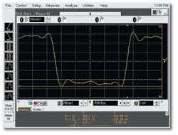
Figure 1 shows a 500-MHz clock signal captured using an Agilent 54855A 6-GHz Oscilloscope. In this case, the signal has been captured with the waveform scaled within the scope�s dynamic range.
Figure 1. Ripple Captured at 100 mV/div
With approximately five divisions of peak-to-peak deflection at 100 mV/div, the entire waveform has been optimally scaled to be fully on-screen. For this particular measurement, we are using slightly more than half (7 b) of the scope�s 8-b ADC. But if we are primarily interested in accurately measuring just the peak-to-peak ripple on the bottom of this signal, then we are using an even smaller portion of the ADC.
With the scope�s voltage markers, we have measured the ripple on this signal to be approximately 74 mVpk-pk. But we are only using about 7% of the scope�s ADC range for this measurement, meaning that our measurement has a resolution of just slightly greater than 4 b.
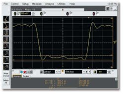
To improve the resolution and apparent accuracy of this ripple measurement, we have used the scope�s vertical DC offset capability and then increased the vertical sensitivity to 20 mV/div to actively zoom in on the bottom of the signal as shown in Figure 2. This should give us a 5� improvement in absolute measurement resolution.
Figure 2. Ripple Captured at 20 mV/div
When comparing the difference between the waveforms captured and displayed in Figures 1 and 2, we see obvious distortions in the captured waveform relative to our first measurement. Some of these distortions are caused by input amplifier saturation, and some are caused by the scope�s Sin(x)/x reconstruction filter due to processing of clipped data points. These types of distortions will occur on all scopes to some degree.
It doesn�t matter how much distortion occurs or what is causing the distortion; any distortion is too much when attempting to improve measurement accuracy. Our intent was to improve measurement resolution and accuracy. But in fact, this measurement technique has degraded our measurement accuracy.
All vendors specify the dynamic range of their scopes. This specification usually is in the range of �4 divisions to �5 divisions depending on the scope. Some scope vendors also specify overdrive recovery time, sometimes called settling time. Overdrive recovery is the time for a signal to recover if the dynamic-range specification is violated.
The recovery-time specification on a multigigahertz oscilloscope can be as much as 20 ns for settling to within 2% of actual signal amplitudes. But for high-speed digital signals, 20 ns can seem to be a lifetime. This gross specification should be a warning to the scope user: Never overdrive the input amplifier when making critical vertical and timing measurements.
Agilent does not have an overdrive recovery/settling time specification for its 6-GHz oscilloscope. This scope has been optimized for the most accurate measurements with the signal always scaled on-screen, which is approximately 90% of the full dynamic range of the 8-b ADC and input amplifier.
Regardless of which vendor�s scope you may be using, never scale the signal under test so that the input signal overdrives the scope�s input amplifiers. So, how should these types of measurements be performed to achieve the most accurate results when measuring small signal perturbations on high-speed digital signals�without overdriving the input amplifiers?
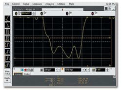
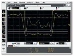
Figure 3 shows the proper measurement. Using waveform averaging, measurement resolution on small signal perturbations can be increased significantly. Unfortunately, display resolution on most DSOs is limited to approximately 8 to 9 b.
Figure 3. Ripple Measurement Using Waveform Averaging and Magnification
To see and more accurately measure these small perturbations, use the scope�s waveform math functions to digitally magnify the waveform around the portions of the signal of interest after averaging. With the input signal scaled to be within the scope�s dynamic range (yellow/bottom trace), digital magnification performs a software expansion of the captured waveform (green/top trace) to reveal additional vertical resolution beyond the 8-b resolution of the scope�s ADC when averaging is used.
This technique does not overdrive the input amplifiers and will not induce any signal distortions due to scope amplifier saturation. The net result is higher resolution and more accurate measurement of small perturbations on larger signals.
We now measure approximately 74.3 mV of peak-to-peak ripple. This should be more accurate than our original 74-mV measurement.
There is a familiar joke where a patient says to his doctor, “Doctor, it hurts when I bang my head against the wall.” The doctor responds, “Well then, don�t bang your head against the wall.”
The same could be said about the problems associated with overdriving a scope�s input amplifier. If you don�t want to make inaccurate measurements, then don�t overdrive the amplifier. Use waveform averaging and digital magnification to make the most accurate measurements on signal perturbations, regardless of which scope you may be using.
About the Author
Johnnie Hancock is an applications engineer with the Design Validation Division of Agilent Technologies. He began his career with Hewlett-Packard in 1979 as an analog and digital hardware designer and holds a patent for digital oscilloscope amplifier calibration. Mr. Hancock graduated from the University of South Florida with a degree in electrical engineering. Agilent Technologies, Design Validation Division, 1900 Garden of the Gods Rd., Colorado Springs, CO 80901, 719-590-3183, e-mail: [email protected]
Return to EE Home Page
Published by EE-Evaluation Engineering
All contents � 2004 Nelson Publishing Inc.
No reprint, distribution, or reuse in any medium is permitted
without the express written consent of the publisher.
April 2004


