A Digitizer-Based Ultrasonic Flaw-Detection System

Small, fast ultrasound reflections require both high-speed and high-resolution digitizing as well as sufficiently deep memory to hold all the data.
A company that manufactures ultrasonic flaw-detection systems used for nondestructive testing of laminar steel parts had been performing all measurements using analog circuitry. But to survive in today�s competitive market, a modernized PC-based system that provided higher performance at a lower cost was needed, one that capitalized on the benefits of high-speed digitizers.
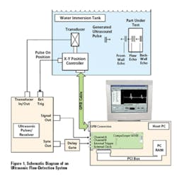
Before discussing the role of today�s digitizers in fault detection, let�s begin with an overview of the system. A commercial broadband ultrasonic transducer is robotically positioned in front of a part under test, with both the transducer and part immersed in a water tank. The transducer, operating in the reflection mode, generates and detects ultrasound. Excited by an ultrasonic pulser/receiver unit, the transducer emits a wideband burst of ultrasonic energy and receives echoes reflected from the part.
Between successive ultrasonic record acquisitions, a robotic positioning arm controlled through a GPIB connection laterally displaces the transducer in 0.1-mm steps. The arm scans through a 500 mm � 500 mm rectangular mesh in a back-and-forth, raster-like pattern so there is a fast and an orthogonal slow axis. While the transducer is translating along the fast axis, the positioning system continuously displaces the transducer in a step-like fashion at a regular rate of about 1 step/ms.
The position controller is equipped with a pulse on position output, a standard feature on many position controllers used in ultrasonics. The controller produces a TTL pulse at the instant when it has stabilized at its target position.
This pulse is used to trigger the ultrasonic pulser/receiver to emit an excitation pulse. In this way, ultrasonic inspection automatically is performed only at the target position.
After excitation of the transducer, the relevant ultrasonic echo trains take about 700 �s to return since the ultrasound must traverse a meter-long water path. A programmable delay gate is used to create a TTL pulse that occurs 700 �s after the ultrasonic excitation. This pulse triggers the digitizer. The ultrasonic echo trains of interest then occur over a period of up to 100 �s.
The Role of the Digitizer
An embedded digitizer is used to capture ultrasonic signals from the transducer electronics. The system incorporates ultrasonic transducers with center frequencies of up to 10 MHz and samples ultrasonic signals at 100 MS/s. This sampling rate provides 10 points per signal cycle, which allows excellent echo timing resolution. To detect flaw echoes that are as small as possible, the highest available dynamic range and vertical resolution are required.
The �1-V signal output from the ultrasonic pulser/receiver is connected directly to the BNC signal input of the digitizer card. A digitizer input impedance of 50 ? can be programmed. This provides input termination that matches the 50-? impedance of the BNC cable, eliminating distortions due to multiple signal reflections. The output of the delay gate is connected to the BNC external trigger input of the digitizer.
The digitizer provides 14 b of vertical sampling resolution. High vertical resolution is imperative in ultrasonic nondestructive testing because of the arbitrarily small amplitude of detected flaw echoes.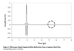
Figure 2 shows a real ultrasonic signal detected from a laminar steel part. The plot illustrates the large echo reflected from the front wall of the part followed by a small echo that indicates a flaw just below the surface. The time by which this flaw echo trails the front-wall echo is directly related to the depth of the flaw through the relation:
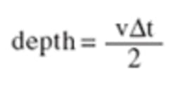
The goal of the ultrasonic scan is to determine ?t throughout the scan and produce a color-coded map indicating flaw depths throughout the part.
The amplitude of the trailing echo grows with the size of the flaw. The overall ultrasonic signal amplitude is adjusted using the gain control of the pulser/receiver so the front-wall echo almost saturates the input range of the digitizer, �1 V in this case.
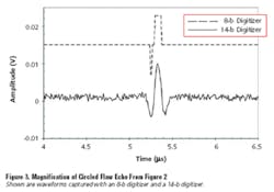
As a result, the small flaw echoes cannot be further amplified without clipping the front-wall echo. Figure 3 shows a magnified view of the small flaw echo from Figure 2. The top waveform is at 8-b resolution and the bottom waveform at 14-b resolution.
The amplitude of the flaw echo is only about 1% of the amplitude of the large front-wall echo. The 8-b digitizer divides the input range into 28 = 256 different levels. This explains the step-like appearance of the 8-b echo from Figure 3, which only spans two or three levels. The echo is severely distorted and, if it were any smaller, would not have been detected at all.
By contrast, the 14-b digitizer divides the input range into 214 = 16,384 different levels. The flaw echo now spans 150 levels. As shown in Figure 3, the 14-b digitizer�s high resolution reproduces the form and position of the small echo. Even if the echo were comparable to the background noise, its time delay, ?t , still could be extracted using numerical cross-correlation analysis. Clearly, high digitizer resolution is crucial for detecting small flaw echoes.
During linear scans along the fast axis, ultrasonic triggers occur at a regular 1-kHz rate. The digitizer must not miss any of these triggers otherwise correspondence between captured waveforms and transducer position will be lost.
Linear scans along the fast axis take (500 mm/0.1 mm)/1 kHz = 5 s. Initiation of the next fast-axis scan is programmable; however, for mechanical reasons, repositioning of the slow-axis motor must take at least 0.5 s.
Acquisition Memory
A problem occurs, however, with operation under MS Windows. Multitasking Windows is not a real-time operating system. Consequently, the amount of time during which a given task or process is interrupted while Windows services other tasks is indeterminate. As a result, no repetitive waveform capture performance can be guaranteed under Windows. Guaranteed, reliable performance is paramount during the system�s fast-axis scan, where not even a single trigger can be missed.
The solution for this requirement is ultra-deep onboard acquisition memory. Operating the digitizer in the multiple-record mode, successively acquired waveforms are stacked in onboard acquisition memory. Between acquisitions, the digitizer is re-armed by the hardware with no CPU intervention required. Consequently, once initiated, the multiple-record mode operates in a fashion that is not compromised by the multitasking Windows environment.
The digitizer will require enough onboard acquisition memory to hold data from an entire fast-axis scan. To determine the amount of memory required, the number of samples in a single 100-�s ultrasonic record must be calculated:
Record Length = 100 �s � 100 MS/s
= 10,000 S = 10 kS
Since the position step size is 0.1 mm and the fast-axis length is 500 mm, there are 5,000 position steps in one linear fast-axis scan. The digitizer must capture one 10,000-S record per position step. As a result, the onboard acquisition memory must be at least
5,000 records � 10,000 S/record = 50,000,000 S
The digitizer, with up to 1 GS of onboard acquisition memory, accommodates this requirement.
Between successive fast-axis scans, the system will download data from the previous fast-axis scan to PC RAM. The digitizer can transfer data through the PCI bus using a method called PCI Bus Mastering. Using this method, no CPU mediation is required during the data transfer, and the digitizer can achieve sustained transfer rates of up to 100 MB/s. Since there are 2 B per 14-b sample, the transfer of all data from a fast-axis scan will take at least
2 B/S � 50,000,000 S/(100 MB/s) = 1 s
Consequently, the data transfer will not drastically delay the onset of the next fast-axis scan since the positioning system already requires 0.5 s of mechanical stabilization time. If the data-transfer process is briefly interrupted by Windows, the transfer time increases slightly but no data is lost, and once reactivated, the transfer process simply picks up where it left off.
A Windows 2000-based application was written in C using a software-development kit. This kit provides convenient, easy-to-use sample programs that serve as a starting point for a custom Windows application.
Since the digitizer card is a PCI plug-and-play device, low-level configuration details are handled by Windows. No low-level hardware programming is required. The Windows application sets up the scan of the part under test, controls the positioning motors, and then calls C subroutines to acquire and download data from the digitizer.
Today�s high-performance PC-based digitizers provide the high sampling speed, high vertical resolution, deep acquisition memory, and fast data transfer that allow construction of automated, low-cost nondestructive testing inspection systems.
About the Author
Andrew Dawson, Ph.D., joined Gage Applied Technologies in 1997 as an applications engineer and has been worldwide sales manager since 2003. Previously, he worked for three years as a research officer at the Industrial Materials Institute, part of the Canadian National Research Council. Dr. Dawson received a doctorate in experimental solid-state physics from McGill University in 1994. Gage Applied Technologies, 1 Provost, Suite 200, Lachine, QC H8S 4H2, 514-633-7447, e-mail: [email protected]
September 2004
About the Author
Comment About the Article
To join the conversation, and become an exclusive member of Electronic Design, create an account today!

Leaders relevant to this article: