The 20+ PCBs on board diesel locomotives survive a very tough combination of functional and environmental testing before they leave the roundhouse.
Like automobiles, locomotives have become high-tech electronic products that require extensive testing. Today�s typical diesel locomotive has 20+ electronic circuit cards, most of which are microprocessor based.
The circuit cards perform a multitude of tasks including controlling the engines, communicating with other locomotives, controlling and monitoring the wheels on the locomotive and the train cars, managing the sophisticated braking system, monitoring numerous safety-related sensors, and interfacing with the engineer via an array of multifunction displays. The complexity of these cards requires a mixed-signal tester capable of handling analog and digital signals as well as various communications protocols.
These cards operate in a harsh environment not typically found in automotive testing. In fact, the environment closely resembles that of military products with temperatures ranging from -45�C to +85�C and high levels of relative humidity. As a result, the testing of these cards is more challenging than that in other industries.
While other industries may be satisfied with production or service testing that includes in-circuit test (ICT) followed by functional test, locomotive testing requires additional functional test while the products undergo environmental stress screening (ESS). The reason: some products may operate flawlessly under standard ambient temperatures but still may fail when subjected to temperature extremes, temperature shock, or high levels of humidity. This temperature test requirement represents a major challenge from technical, logistic, and financial perspectives.
Technical
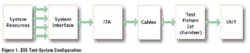
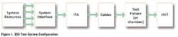
The typical test system includes the mainframe, providing the system resources such as measurement, stimuli, digital, communications, power, and switching. These resources are routed to the system�s interface where an interface test adapter (ITA) connects them to the unit under test (UUT) via interconnect cables if the UUT is a box-type instrument or a special fixture if the UUT is a circuit card.
Testing circuit cards in a temperature chamber usually requires that long cables be used from the ITA to the UUT. These cables may degrade the signals and, in some cases, may cause the UUT to malfunction.
The typical test-system configuration wouldn�t work in the case of temperature testing the locomotive PCBs. A special fixture is needed to be in close proximity to the UUT. The solution is to place the special fixture outside the chamber but enable the UUT to plug directly into it as shown in Figure 1.
Another technical challenge is the complexity level of the UUTs themselves. While some of the UUTs are simple analog input/analog output boards handling various sensors, some of the boards contain multiple communications channels, and most are CPU based.
The functional test of a microprocessor-based UUT is complex by itself, but troubleshooting such a board is significantly more difficult. For this reason, a test system that provides troubleshooting capabilities for CPU-based boards must include a ROM emulator.
The ROM emulator connects to the UUT�s boot ROM, disables the ROM, and acts as the boot ROM itself. Subsequently, the CPU is slaved to the ROM emulator and, while it runs at the standard clock speed, it is under the control of the test system.

Logistic and Financial
While the functional test itself may only take minutes per board, the test sequence under temperature extremes is significantly longer. Not only does the chamber have to reach the desired set point, the UUT needs to soak in the temperature for a period of time before the testing starts to ensure that the UUT temperature is at the desired set point.
A typical functional test at temperature extremes includes both high- and low-temperature tests. Assuming a high-performance chamber is used, the overall test time for a single UUT is significantly longer than the 10-minutes required for a functional test at high and low temperatures; more than 2� hours as Table 1 suggests.
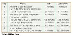
For low-volume production, the test times presented in Table 1 may be acceptable, but this is not the case for any medium- to high-volume environment. To reduce test time, a fixture capable of accommodating more than one UUT must be used. Even if the test set does not have the resources to test multiple UUTs concurrently, having the fixture will ensure that the ESS overhead, 2� hours in this case, is shared among several units and does not apply to each one.
An example of this approach was implemented in a recent test set developed for a major U.S. locomotive manufacturer. The customer needed a functional test set capable of testing 20+ different UUTs in a chamber. Due to the ESS overhead shown in Table 1, it was clear that testing one UUT at a time would not be effective.
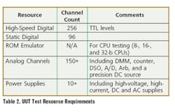
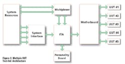
Because of the complexity of the UUT, it was not feasible to design a test set with sufficient resources to test multiple units (Table 2). The solution included a PXI-based system with sufficient resources to test any UUT and a custom multiplexer to allow parallel testing of five UUTs at a time. The configuration of the resultant PXI-based system was quite complex, especially due to the high channel count and the requirement to test many different types of UUTs, some analog, some digital, and some mixed signal.
To simplify the configuration, some signals were routed directly to the multiplexer while others were sent to a general-purpose ITA designed to allocate system resources to the UUT with the help of a personality board. To minimize the effects of long wires on the high-speed TTL lines, the PXI-based digital I/O boards used differential LVDS signals routed to the multiplexer and then converted to TTL a short distance from the UUT�s connectors. The configuration of this system is depicted in Figure 2.
To handle the temperature requirements, a temperature controller is connected to a hood mounted over the UUTs as they plug into the motherboard. The temperature is controlled by the test set via GPIB. Figure 3 is a block diagram of a sample UUT. The UUT is a communications card with multiple channels and some analog I/O.
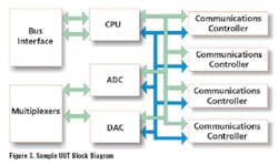
This UUT needed multiple mixed-signal resources for functional testing. Required resources include:
-
High-Speed Digital I/O: To emulate the UUT�s bus interface and interface with the four communications controllers.
-
ROM Emulator: To test and troubleshoot CPU circuitry and identify kernel faults.
-
Analog Measurement and Stimuli: To provide signals needed for the A/D test and measure voltage generated by the D/A converter.
-
Switching: To multiplex the analog inputs and outputs and provide a mechanism to perform safe-to-turn-on tests.
-
Power: To provide UUT operating power and capabilities to measure current drawn by the UUT.
Due to the amount of resources needed to support 20+ different UUTs and the high channel-count, the test set uses two 20-slot, 6U PXI chassis; a GPIB DSO; and AC and DC GPIB power supplies. The system is controlled by an embedded PXI controller, and a PXI bus expander controls the second PXI chassis.
About the Author
Loofie Gutterman, co-founder of Geotest-Marvin Test Systems, has more than 20 years of experience in the test and measurement industry. At Geotest, he has served in many positions ranging from vice president of systems engineering to COO and now president. Previously, Mr. Gutterman was employed at RSi for several years as a program manager, COO, and technical director. Geotest-Marvin Test Systems, 17570 Cartwright Rd., Irvine, CA 92614, 949-263-2222, e-mail: [email protected]
September 2004
About the Author
Comment About the Article
To join the conversation, and become an exclusive member of Electronic Design, create an account today!

Leaders relevant to this article: