ESD Test Epuipment – HBM Device Failure- The Scourge of Static-Sensitive Operations

This close examination of S20.20 reveals the key ingredients to a successful ESD control program.
Multinational manufacturing corporations are racing to pursue the cost benefits of economic geography. In fact, by 2005 as much as 70% of all manufacturing operations will be located in Asia. As part of this dramatic evolution, the impact of ESD is estimated to become the third largest problem in electronic manufacture and device handling.
Enlightened managers know that ESD affects primary assembly and their product warranty as well as the electronics industry in general. Those understanding how ESD influences their process will be the beneficiaries of stable productivity, enhanced product reliability, and an enviable bottom line.
With devices having evolved to their smallest configurations and fastest, most sensitive structures in 30 years, onboard circuit protection currently is very limited. To achieve ESD protection, controls must be built into the process and handling environment more so than ever before.
While it is true that automation is a large part of the process, discharges described by the Human Body Model (HBM) remain a major source of ESD failure. HBM, along with its higher speed and power cousins, Charge Device Models (CDM) and Machine Model (MM), accounts for international ESD losses that now exceed an estimated $90 billion. Yet, the industry spends far less than $2 billion trying to resolve this insidious problem.
Two years ago, the Electrostatic Discharge Association (ESDA) announced the availability of third-party certification to the ANSI/ESD S20.20 Standard for the Development of an Electrostatic Discharge Control Program. This milestone document includes specific guidelines for developing an efficient ESD control program for effective device protection. To date, more than 70 corporations have received independent certification, and as many as 1,000 facilities will be certified by 2007.
Close examination of this document reveals the key ingredients to a successful program. One of them is proper personnel grounding. In addition to wrist straps, the document offers options for grounding via footwear and flooring and controlling body-voltage generation.
Personnel Resistance To Ground In the S20.20 ESD Program Manager Certification Course, ESDA Standards Chair Ron Gibson emphasized that body voltages always are being generated and that wrist straps minimize the effect of these transients based on the body's actual resistance to ground. While quality wrist straps offering 1 MΩ to ground limit body voltage to approximately 10 V or less, degraded wrist straps with 35 MΩ to ground will allow body voltages of up to 100 V. S20.20 requires personnel resistance to ground be less than 35 MΩ. For those handling components with greater sensitivity to ESD, it may be prudent to reduce the voltage and resistance limits.Resistance Measurement of Personnel to Ground
As part of its tailoring approach, S20.20 allows a means for grounding via footwear and flooring to provide personnel mobility during transport and while standing at a machine or workstation. S20.20 also requires the use of wrist straps when personnel are seated and handling ESD-sensitive devices.
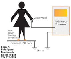
The reference for measuring the personnel system resistance to ground is defined in ESD STM 97.1-1999 Floor Materials and Footwear Resistance Measurement in Combination With a Person. This basic measurement requires a wide-range ohmmeter and appropriate leads and grounding accessories. The ground point for the measurement should be tested before use in accordance with local codes and ANSI/ESD STM 6.1-1999 Grounding Recommended Practice. The ground point may be a previously tested ESD common-point ground or an equipment ground reference.
With the test subject wearing ESD control footwear and standing on an ESD control floor, measure the resistance from the hand to the selected ground point using 10 V for the test voltage (Figure 1). This measurement takes into account the individual's body resistance, footwear, and floor resistances.
If body voltage is the primary control element, the document requires that a proper measurement in accordance with ESD STM 97.2-1999 Floor Materials and Footwear Voltage Measurement in Combination With a Person confirms this level of performance.
Measuring Body-Voltage Generation
Measuring body-voltage generation is not difficult and, with practice and simple calculations, offers an insight to projecting typical body voltages that could be experienced in a given facility. The procedures also are useful for evaluating footwear, floors, or both to obtain the best combination for the lowest voltage generation prior to purchase.
Measurement setup requires a charge plate monitor (CPM); an X-Y recording device; a long, high-quality test lead; and a few accessories. In effect, the operator will make several specific walking steps while connected to the CPM. The recorder documents the operator's generated walking voltage for later analysis.
There are several instrument options for this measurement. You might use a standard 20-pF CPM or a portable system suitable for the measurement. Recording devices may be a strip-chart recorder, an X-Y plotter, or an analog-to-digital converter connected to a computer.
Regardless of instrument selection, the measurement records a six-step walking pattern that provides data used for projecting two probable ranges of human body voltage generated in the following situations (Figure 2):
• The maximum probable voltage generated while walking and transporting ESD sensitive devices.
• The minimum standing body voltage seen at machines and workstations after walking and before touching the facility's most ESD-sensitive device.
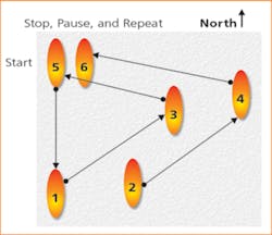
The six-step pattern compensates for the fact that everyone walks differently. Repetitive patterns provide relative data that can be statistically assessed to approximate the range of probable voltage generation experienced with any combination of footwear and floors.

Each walking pattern is identified, and maximum and minimum absolute values are defined. Once the values are defined, there are three approaches to evaluating the data:
1. ESD STM 97.2-1999 simply requires that the three maximum values be identified. If the peak values are less than 100 V, the footwear-floor combination generally is considered acceptable, particularly for protecting devices having HBM voltage thresholds well above 100 V.
While the standard's working group confirmed that various operators would obtain similar results, this approach does not mathematically account for the differences in operator capacitance or project probable body-voltage generation that might be anticipated by others. This approach also does not address how you would assess the data for protecting ESD devices having HBM sensitivities well below 100 V.
2. Stephen Halperin & Associates developed a test method in the mid 1980s to assess performance of new ESD control floors and footwear. To this end, a Gaussian distribution data analysis was conducted to ascertain the percent probability of equaling or exceeding any given walking or standing body voltage with ESD footwear and flooring products.
Ultimately, the materials combination was evaluated by calculating the maximum probable voltage generated beyond which there is a zero-percent probability that additional voltage could be generated under the test conditions. This proved far too complicated for the typical plant audit environment and required additional training in data analysis for test operators.
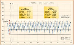
3. To simplify the data analysis in the ESD audit environment, identification of the maximum and minimum data points can be used to calculate the probable body voltage generation ranges during walking and standing. This analysis is illustrated in Figure 3.
Shoes Acme Model# XP4300 Floor Samson # 8900 Carpet Title
Operator: S. Halperin
30Jan 2004 13:43Figure 3. Sample Analysis of Six-Step Walking Patterns to Project Ranges of Walking and Standing Body-Voltage Generation
Maximum Walking Voltage Range
Calculate the average and stand-ard deviation of maximum voltage peaks, multiply the standard deviation by three and add it to the average to obtain the probable top end of the maximum body-voltage range, then subtract three times the standard deviation from the average to obtain the probable bottom end of the maximum body-voltage range.
Typical Standing Voltage Range
Calculate the average and stand-ard deviation of minimum voltage values, multiply the standard deviation by three and add it to the average to obtain the probable top end of the standing body-voltage range, then subtract three times the standard deviation from the average to obtain the probable bottom end of the standing body-voltage range.
Referring to Figure 3, the maximum walking voltage is a negative value; that is, the footwear-floor combination generates a negative charge on the operator. At the moment the operator pauses after Steps 5 and 6, body voltage approaches and slightly exceeds the zero line. The average walking voltage is -47.29 V, and the standard deviation of the maximum peaks is 5.08 V.
Also from Figure 3, the probable maximum walking body-voltage generation range of plant personnel would approximate -32.0 V to -62.5 V. The minimum voltage would be about -5.5 V to 15.0 V while personnel worked standing at machines and workstations.
Knowing the probable voltage-generation ranges, we can adjust our process to maximize ESD protection from HBM events. For example:
• With a worst-case device HBM sensitivity of 100 V, we can safely handle the device while standing at the workstation or transport it through the plant environment where ESD footwear and floors are used.
• With an HBM device sensitivity of 25 V to 50 V, we can only handle the device safely while standing at the workstation but must place it in ESD protective packages or containers when transporting it through our environment.
Summary
Understanding personnel resistance to ground allows us to select and use wrist straps, footwear, and flooring in a manner appropriate to our most HBM-sensitive device and most compatible with our process. Simple resistance to ground measurements help verify that, once installed, these control products continue to perform at desired levels.
Certainly, the results of body-voltage generation analysis are based on ambient test conditions, operator care in performing the measurements, and the condition of footwear and flooring tested. However, this approach does characterize probable human-body voltage generation in a facility with greater than 90% confidence.
Given that we are aware of the voltage threshold of our most sensitive device, we can reliably predict the potential for HBM damage by human handling. Armed with this knowledge, we also can match our footwear to our floors to obtain the lowest possible voltage generation or know that we need to enhance our controls using effective static-control floor maintenance materials or transport procedures.
Once we have control of our HBM damage threat, we can focus on controlling CDM and MM failures to further reduce potential ESD losses.
About the Author
Stephen Halperin founded Stephen Halperin & Associates in 1983 and Prostat, a supplier of static-control instruments and materials, in 1992. He is a charter member of the ESD Association, has held all elected ESDA officer positions plus that of an elected member of ESDA board of directors for several years, and is past standards chair and past education chair. Mr. Halperin also has written several articles on ESD control and received the ESDA's Outstanding Contributions Award. Stephen Halperin & Associates, 1072 Tower Lane, Bensenville, IL 60106, 630-238-8883, e-mail: [email protected]
About the Author
Comment About the Article
To join the conversation, and become an exclusive member of Electronic Design, create an account today!

Leaders relevant to this article: